 English
 Español
Categories
Contacts
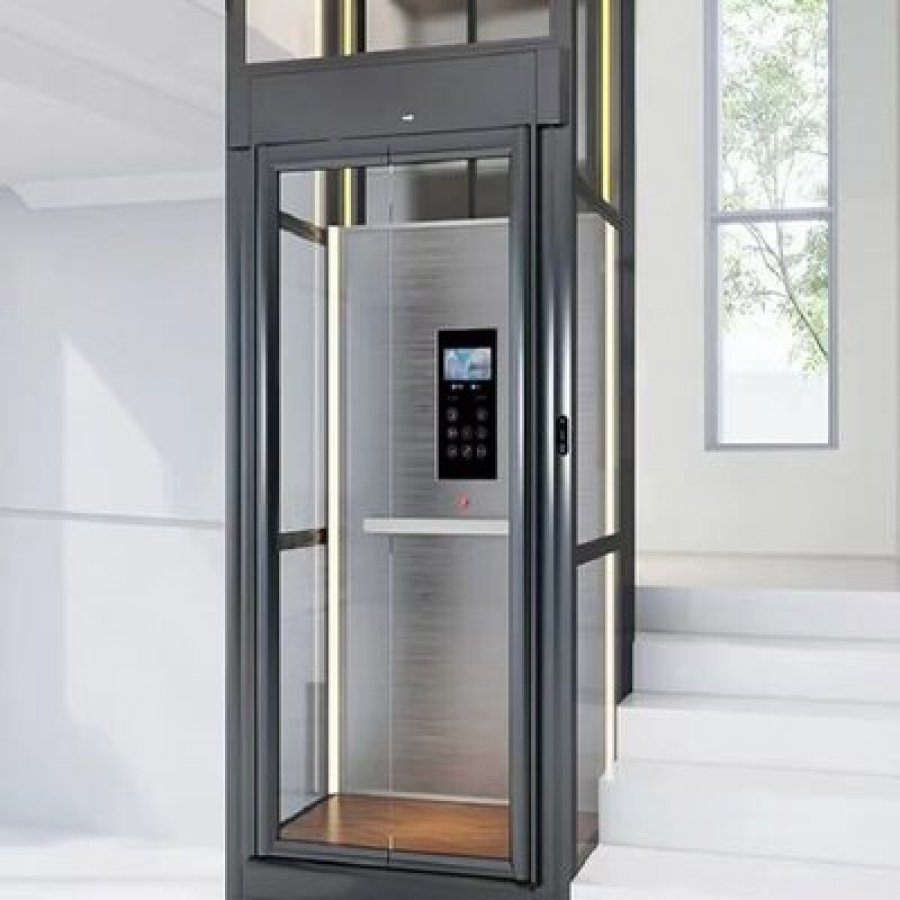
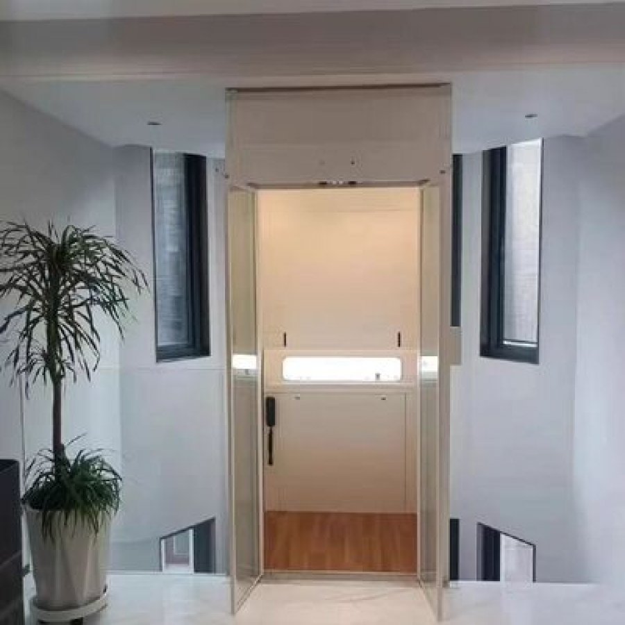
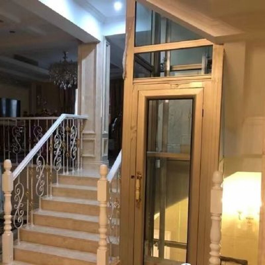
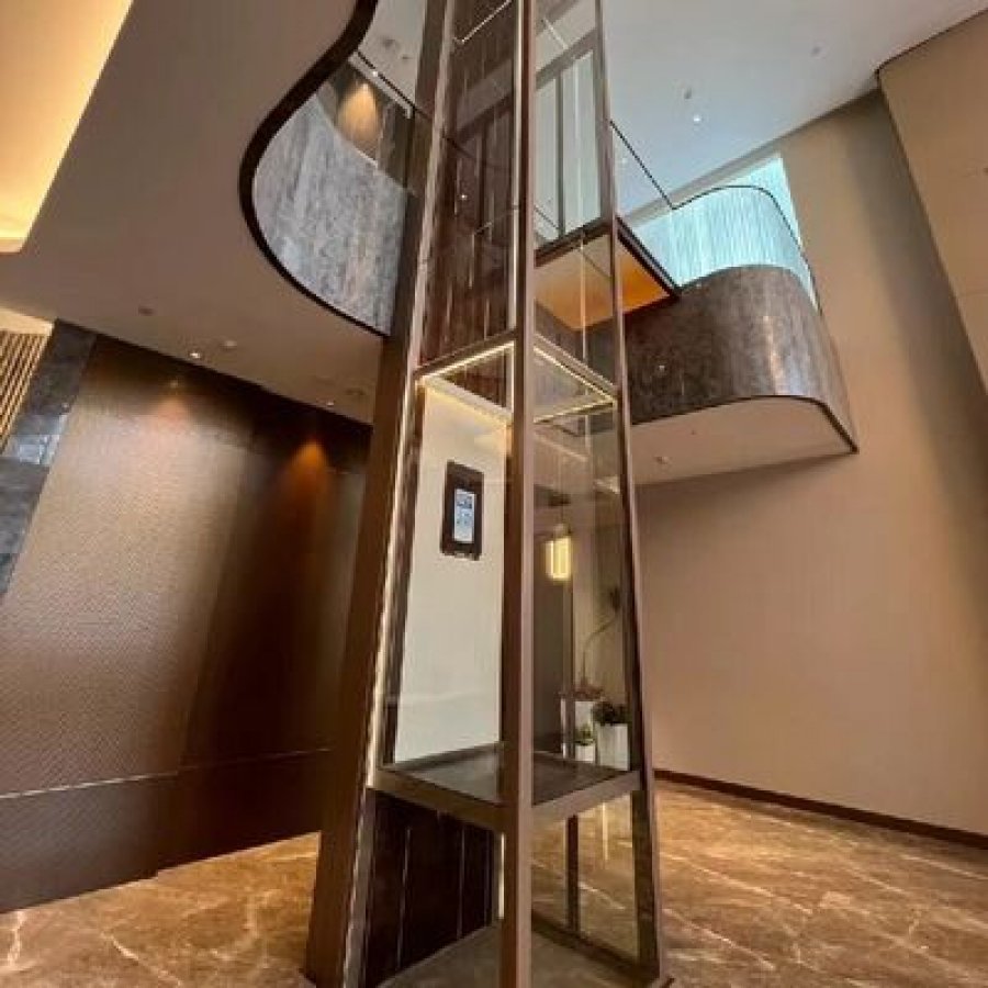
Hydraulic Residential Elevator | 5 Stops for Homes & Villas
Product Details:
Brand Name
YIMEISITE
Place of Origin
China
Payment & Shipping Terms:
Minimum Order Quantity
1 set
Price
USD 4,000-10,000 per set
Payment Terms
T/T,L/C
Supply Ability
20 sets per month
Delivery Time
45 working days
Packaging Details
Export non-fumigation wood box
| Motor: | 4.7 Kw | Power Supply: | Single-phase AC |
| Pit Depth: | 0 M | Cabin: | 304# Stainless Steel/aluminium Alloy |
| Number Of Stops: | 5 Stops | Power: | 220V, 50Hz, Single Phase |
| Max Height: | 14.5 M | Warranty: | 1 Year |
| Highlight: | Apartment Hydraulic Lift At Home,5 Stops Residential Lifts,Apartment Residential Lifts | ||
Product Description
Hydraulic residential elevator · 5 stops · pitless
This page is about one decision: whether a hydraulic residential elevator with five stops, up to 14.5 m of travel and a 0 m pit is the right machine for a particular building. It is not a general essay on how hydraulic lifts work. It answers the four questions that decide most residential jobs. Is five stops still inside the hydraulic range? Is 0.6 m/s fast enough to live with? Can a 220 V single-phase supply carry the machine? And what does a genuinely pitless layout ask of the building after hand-over?
- 5stops, up to 14.5 m of travel
- 400 kgstandard, custom up to 1,000 kg
- 0.6 m/srated speed on the published sheet
- 0 mpit on the pitless layout
- 220 V50 Hz single-phase supply
1. Who this layout suits, and who it does not
A hydraulic residential elevator lifts the car with oil pressure from a power unit rather than with ropes and a counterweight. That single mechanical choice shapes everything else on this page. The car sits on a ram, the machine room is not a room above the shaft, and the load path goes into the floor of the lowest level instead of into a head beam. Five stops and 14.5 m of travel are the published ceiling for this model, and the pitless version removes the excavation that normally makes a retrofit expensive.
Residential buyers rarely arrive with a drive preference. They arrive with a building: a five-storey town house, an apartment block with a stairwell, a villa with a service void. The fit judgement below is aimed at that situation, because a drive that suits one shell will fight another.
Strong fitRetrofit inside an existing shell
- A conversion with four or five levels and a stairwell, void or lightwell that can accept a car.
- An owner who cannot dig a pit and cannot build a machine room above the top landing.
- A single-phase supply already available at the building, which matches the published 220 V configuration.
- Travel within the published 14.5 m, so the hydraulic layout stays inside its rated envelope.
WorkableNew build with a framed shaft
- A villa where the shaft is formed during construction and the finishes are chosen with the car.
- Projects that want a 304 stainless steel or aluminium alloy cabin instead of a builder's box.
- Clients who accept 0.6 m/s as the design speed and plan journey times around it.
- Sites where the shaft geometry is drawn before the lift is ordered, not after.
Wrong toolRead the other pages first
- More than five stops or a travel beyond 14.5 m — the published figures for this model stop there.
- A building where the top landing cannot provide the overhead the drawing asks for.
- An installation that has to be built with no floor-level space at all for the power unit.
- A specification that demands a much higher rated speed than the published 0.6 m/s.
The three cards are not a ranking. They describe which of the three conversations you are actually having: an engineering retrofit, a construction project, or a specification that should be checked against a different machine. Two of the three end with a lift; one ends with advice to look at a different drive.
What a 0 m pit does not remove
- Overhead at the top landing. A pitless layout moves the machine below the car, it does not remove the space above it.
- Floor loading at the base. The ram and the power unit stand on the lowest slab, so that slab has to be able to take them.
- The power unit and its access. Somewhere at the lowest level there is a compact hydraulic unit, and a technician has to reach it.
- Landing sills. Each stop still needs a finished sill and a level threshold at the floor the car serves.
If those four points are already answerable from your drawings, the rest of this page is about confirming numbers rather than changing the design. Section 3 lists every published figure in one table and marks where each one comes from; section 9 compares the hydraulic layout with traction and screw drives so the choice is made on the building, not on habit.
Everything quoted on this page comes from the specification table published alongside this model: rated capacity, number of stops, travel, speed, pit depth, power supply, motor rating, cabin material, safety devices and warranty. Where a figure is not published, this page says so instead of borrowing a number from another model.
2. Five stops, 14.5 m and 0.6 m/s: what the numbers mean in a house
Three published figures decide how a residential hydraulic elevator feels in daily use: the number of stops, the travel it covers, and the rated speed. The sheet gives five stops, up to 14.5 m and 0.6 m/s. Read together, they describe a low-rise building with generous floor heights rather than a slow lift struggling through a tower.
Five stops means four intervals between the lowest and the highest landing. Split the published 14.5 m across those four intervals and the average distance between stops works out at roughly 3.6 m. That is a comfortable residential floor-to-floor height, which is why the layout is usually quoted for four- and five-storey houses, town houses and small apartment buildings rather than for anything taller.
What 0.6 m/s actually feels like
Speed is easier to judge as time than as a number. A car that covers a full 14.5 m at 0.6 m/s spends about 24 seconds moving. A single storey of 3.6 m takes about 6 seconds of drive time. Most residents judge the lift on those short hops, because that is how the lift is normally used: one or two floors, a few times a day.
An honest reading of those bars matters more than the bars themselves. The published sheet gives a rated speed and a travel; it does not publish door open and close times, acceleration ramps or levelling time. Anyone who tells you that a five-stop lift takes exactly X seconds door to door is quoting a figure that this specification does not contain. The reliable way to judge is to measure a running installation, or to add the delivered door cycle to the numbers above during commissioning.
Work out your own trip time
Use the calculator below with your own floor heights. It applies the published 0.6 m/s to the travel you enter, and it deliberately ignores door dwell, so treat the result as the drive's share of the journey rather than the total wait.
The default 3.6 m is the average interval implied by the published 14.5 m over four intervals. The calculator flags any combination that passes the published travel limit for this model; it does not predict door dwell, dispatching or waiting time.
Three phrases that describe the same layout
Buyers reach this layout through three different phrases. Some search for a pitless residential elevator because the excavation is the problem they are trying to solve. Others look for a 5 stop residential lift because their building has five levels and they want to know whether one machine can serve all of them. A third group arrives looking for a residential lift single phase supply, because the building has a domestic supply and no realistic route to three-phase power. All three describe the same published configuration on this page, and all three are answered by the same three numbers.
That overlap is worth stating plainly, because it explains why this model is quoted so often for town houses and small apartment buildings. A five-stop layout with no pit and a domestic supply is the combination that existing buildings can usually accept without structural work.
If the numbers above describe your building, the specification table in the next section is the one to check line by line. If your travel sits well beyond 14.5 m, stop here and send the drawing instead — a different drive will be quoted.
3. Specification overview for this five-stop model
The table below is the working sheet for a project meeting. It carries every figure this model publishes, keeps metric and imperial on the same line so a mixed team can read it, and adds a source column so nobody has to guess where a number came from. Switch units with the control above the table; the sticky header keeps the column meaning visible while you scroll a long row list on a phone or a laptop.
| Item | Published value | Source |
|---|---|---|
| Rated capacity | 400 kg880 lb, custom up to 1,000 kgup to 2,200 lb | Specification table on this page |
| Number of stops | 5 | Specification table on this page |
| Maximum travel | 14.5 m47.6 ft | Specification table on this page |
| Rated speed | 0.6 m/s118 ft/min | Specification table on this page |
| Pit depth, pitless layout | 0 m0 in | Specification table on this page |
| Door type | Automatic sliding | Specification table on this page |
| Drive and control | Hydraulic drive with microprocessor control | Specification table on this page |
| Motor rating | 4.7 kW6.3 hp | Specification table on this page |
| Power supply | 220 V, 50 Hz, single phase | Parameter table beside the product photo |
| Cabin material | 304 stainless steel or aluminium alloy | Specification table on this page |
| Safety devices | Emergency stop, overload protection, brake | Specification table on this page |
| Warranty | 12 months | Specification table on this page |
| Certification | CE declaration and ISO 9001 quality-management certificate issued with the shipment | Stated for this model; documents travel with each unit |
| Brand and origin | YIMEISITE, China | Parameter table beside the product photo |
How to read the source column
Two of the rows come from the parameter table beside the product photograph, because that is where the commercial and supply information sits. The rest come from the model's own specification list. Keeping the two apart matters when a drawing is checked: a supply voltage and a brand name are quoted from the parameter table, while capacity, travel and speed are engineering figures from the specification list.
What this table proves
Five stops, 14.5 m, 0.6 m/s, a 0 m pit on the pitless layout, a 4.7 kW motor on a 220 V single-phase supply, and a 12-month warranty.
Not in this table
Shaft and car dimensions, overhead clearance at the top landing, door open and close times, and a service interval. None of these are published for this model.
What it means for your drawing
Shaft size and overhead are confirmed against the drawing issued for your project, and the finished dimensions are the ones to build to.
Where the business terms live
Minimum order, price, payment terms, supply ability, delivery time and packaging stay in the parameter table beside the photograph, so this page does not repeat them.
Read the two "does not contain" lines as a warning rather than a gap. A shaft size copied from another project is the most common reason a residential lift has to be re-designed after the order, and the table above is deliberately built so you can see which figures are yours to confirm.
Certification wording on this page is limited to the documents that travel with the unit. No certificate number, notified body or local approval is claimed here, because none is published for this model.
4. Apartment retrofit and villa new build: two different jobs
The same five-stop machine arrives at two very different sites. One is an existing apartment building where the shaft, the floor levels and the electrical supply are already fixed by somebody else's design. The other is a villa or a house where the shaft can still be shaped around the lift. Treating them as one project type is the fastest way to lose a week on site.
Retrofit: the building sets the rules
Levels, sills and the stairwell opening already exist. Surveying happens before quoting, and the pitless layout is the reason the project is workable at all.
New build: the drawing sets the rules
The shaft is formed to the issued drawing, the car is finished to match the interior, and the supply is planned while the services are still open.
Both cases share one rule
Someone measures the building and signs off the shaft dimensions before the lift is ordered. Everything after that is execution.
Retrofitting a five-storey apartment building
The published travel of 14.5 m is what makes a five-stop retrofit realistic. Building regulations, lease documents and the geometry of the stairwell decide the position of the car long before the drive does, and the 0 m pit matters because excavation inside an occupied building is disruptive and often impossible.
- Survey the levels first: the difference between the lowest and highest landing has to sit inside the published travel.
- Decide where the hydraulic power unit will live, and how a technician reaches it later.
- Confirm the slab that carries the ram and the unit, and the finished sill at every landing.
- Check the electrical supply against the published 220 V single-phase configuration and ask the electrician to size the circuit from the motor nameplate.
- Plan the landing doors and the lobby finishes, because those are the parts residents see every day.
A villa or a house where the shaft is still open
On a new build the sequence reverses. The shaft is formed to the issued drawing, the overhead at the top landing is designed in, and the car is specified with the rest of the interior. A five-stop layout covering up to 14.5 m usually means basement to second or third floor, with the car running through a stairwell that is already the vertical spine of the house.
- Fix the shaft drawing before the walls are closed, and keep the landing levels in the same coordinate system as the lift drawing.
- Choose the cabin material early, because 304 stainless steel and aluminium alloy take different finishes at the edges.
- Reserve the power unit position at the lowest level and keep the route to it clear.
- Bring the single-phase supply to the unit position while the first fix is open, and leave the circuit labelled.
- Decide about the landing doors and the car interior together, so the finished thresholds match the floor.
Four failures seen on site
- Levels measured after the lift was ordered, so the total travel no longer matched the building.
- A power unit position chosen for the installer's convenience and later blocked by a plant room or a store.
- A three-phase supply assumed to be a problem for a machine published at 220 V single phase, or the reverse, decided without checking the meter.
- Car interior chosen after the shaft was tiled, which forces a compromise on the very finish the owner cares about.
None of these failures are drive-related. Each of them is decided in the first two weeks of a project and each of them is cheap to fix at that point. The next section deals with the supply question, because that is where residential projects most often discover a problem late.
5. The 220 V single-phase supply, and how to check it
Power is the quiet advantage of this model. The published configuration is 220 V, 50 Hz, single phase with a 4.7 kW motor, so the lift does not need a three-phase supply brought into a house that never had one. On a retrofit, that single line often decides whether the project is affordable: running three-phase power to an existing building can cost more than the lift itself.
It also changes who can help. Any competent electrical contractor can work on a single-phase circuit, so the supply is not a specialist conversation. What still has to be done properly is the circuit design around the machine.
What the published sheet gives you
A motor rated at 4.7 kW, a 220 V 50 Hz single-phase supply, and microprocessor control with its own low-voltage logic. The power unit and the control cabinet can be planned from those three facts.
What your electrician confirms
The dedicated circuit, its protective device and the cable run, sized from the motor nameplate that ships with the unit rather than from a rule of thumb borrowed from another project.
What the site confirms
That the supply is not already loaded to its limit, that the route to the power unit is accessible, and that the isolation point is where a service technician can reach it safely.
The reason the nameplate matters is that a motor's supply current is not simply its power rating divided by its voltage. Power factor and efficiency both sit in that calculation, and the delivered motor may differ slightly from the rating on the sheet. Sizing a circuit from a number invented on a web page is how a lift ends up tripping a breaker on the busiest day of the year.
Is single phase a compromise?
Not at this rating. The published machine is designed around a 220 V single-phase supply with a 4.7 kW motor, so the drive, the power unit and the control cabinet are matched to it.
What if the building is 60 Hz?
The published configuration is 50 Hz. Where a site runs at 60 Hz or another voltage, confirm the matching configuration with the factory before the order is placed.
What if there is no mains at the site yet?
Plan the supply before the lift is installed. A waiting supply delays commissioning even when the lift itself is finished.
Does the lift need a separate meter?
That is a building question, not a lift question. Where the meter is shared, agree the allocation with the owner before the circuit is wired.
Three supply problems worth avoiding
- A lift circuit shared with heavy domestic loads, so the machine and the load compete for the same protective device.
- Cable runs sized on a guessed distance rather than a measured one, so voltage drops at the power unit.
- Back-up or generator supplies assumed to be compatible without checking how they behave under the starting load of the power unit.
Handled early, the supply is a half-day of coordination. Handled late, it becomes the reason a finished lift cannot be handed over, so it belongs on the same checklist as the shaft drawing rather than in the week of commissioning.
Specifying a residential lift single phase supply also removes a coordination problem that catches larger projects. There is no phase rotation to check, no three-phase panel to fit into a domestic board, and no argument about which phase the lift should sit on. On a retrofit, that simplicity is often worth more than the theoretical efficiency a three-phase machine would offer.
Where the building has three-phase power already, the published single-phase configuration can still be used, provided the circuit is designed for it. What matters is that the decision is made from the supply actually available at the power unit position rather than from an assumption made in an office.
This page publishes the supply, the motor rating and the control type. It does not publish a circuit diagram, a cable size or a protective-device rating, because those are produced for the delivered configuration and signed off by the project's own electrician.
6. Cabin, doors and the finishes people actually touch
Residents never see the power unit. They see the car interior, the door, and the threshold at each floor, so those three items carry most of the perceived quality of a residential lift. The published sheet fixes two of them: the cabin is built in 304 stainless steel or aluminium alloy, and the doors are automatic sliding doors.
304 stainless steel cabin
A brushed or satin stainless finish takes knocks, wipes clean and reads as commercial-grade. It is the usual choice for a service stair or a lift that will see steady traffic.
Aluminium alloy frame
Lighter framing with more freedom at the edges, which suits a car that has to sit inside a domestic stairwell and match painted joinery.
Automatic sliding doors
The published door type for this model. Automatic doors remove the manual handling step and the door position becomes part of the finished wall at every landing.
Door and threshold decisions that outlive the installation
A sliding door leaves no swing space in the landing, which is what makes the layout viable in a narrow stairwell. The trade is that the finished opening has to be built accurately. Frame tolerance, floor level and the final floor finish all meet at the sill. A sill set before the screed is poured is the thing residents will notice for the next twenty years.
- Set the finished floor level at every landing before the sill is fixed, not after the tiles are laid.
- Agree the car interior before the shaft is clad, so the cabin panels and the landing reveals can share the same datum.
- Keep the door pocket clear of pipework and conduit runs that were never drawn.
- Decide the lighting position inside the car early, because the cable route passes through the same wall.
Cabin choice is also the point where two similar projects stop looking alike. Where stainless steel is the direction, read the published stainless-cabin model alongside this page: 304 stainless steel cabin hydraulic home elevator. It shows the same pitless five-stop layout with the cabin finish as the headline difference.
Replacement panels, sills and door parts should be ordered from the manufacturer's parts list. A locally fabricated panel will fit the opening and will not match the original car, and matching a brushed finish later is harder than ordering it once.
7. Safety devices and the hand-over checks
The published safety list for this model is short and specific: an emergency stop, overload protection and a brake. Short lists are easy to verify, which is the point. On hand-over day each one can be demonstrated, written down and kept with the project file instead of being taken on trust.
Read the drawing
Confirm which safety devices the delivered configuration includes and where each one is fitted.
Watch the overload test
Load the car past its rated capacity in a controlled test and confirm the protection stops the machine from running.
Press the emergency stop
Confirm the car stops, the machine stays stopped, and the lift only restarts after the device is deliberately reset.
Check the brake and the doors
Confirm the brake holds the car at rest and that the door behaviour matches the delivered drawing at every landing.
Write it down
Record the date, the device tested, the result and who witnessed it. That record is what a warranty conversation rests on later.
A hand-over is not a demonstration of the drive. It is a list of tests with someone's name against each line, and it is the only moment when every device is guaranteed to be observable at once.
Hand-over checks signed off: 0 / 8 ready
Two of those lines are usually argued about. The isolation point is a building issue that the lift depends on, and the power unit position is the one that gets quietly blocked six months later by a store of garden furniture. Both are cheap to settle on the day and awkward to settle afterwards.
If a device needs adjusting after hand-over, it is worth recording who adjusted it and why. Overload settings and door behaviour get changed by well-meaning maintenance visits, and a written trail is what stops the same adjustment being made twice in opposite directions.
Safety devices on this page are quoted exactly as the model publishes them. Nothing has been added from a different model or from a general elevator norm, and no test result is claimed here.
8. Living with a pitless layout: what maintenance involves
A pitless hydraulic lift is maintained from the lowest level rather than from a pit below it. That changes the routine in a useful way: most of the checks are carried out standing on a normal floor, and there is no pit to drain, ventilate or clean.
What the published sheet does not give is a service interval. That is not an oversight to work around with a guess; it is a number to agree with the service partner at hand-over, written into the maintenance record, and then kept.
A workable maintenance routine
Agree the interval at hand-over
Fix the service interval in writing with the partner who will attend. The published sheet does not state one, so this is a decision rather than a default.
Keep the lowest level clear
The power unit needs reachable space and air around it. A clear floor is the single most useful thing an owner can maintain.
Look for fluid traces
A hydraulic system that leaves a film under the unit or along the ram is telling you something. Report it at the next service rather than topping anything up yourself.
Exercise the lift
A residential lift that runs once a week keeps its door gear and its levelling in use. Occasional cycling is kinder to the machine than months of silence followed by a busy weekend.
Keep door tracks and sills clean
Grit in a sliding door track is the most common cause of a call-out on a residential lift, and it is the cheapest one to prevent.
Log every call-out
Date, symptom, action and part. Over a ten-year life that log is worth more than any single inspection report.
The routine above describes who does what. The engineering content of each visit belongs to the service partner and to the delivered documentation.
Owners sometimes ask whether a pitless layout is harder to maintain than a conventional one. In practice the opposite is often true, because the parts that need attention are standing in daylight at floor level instead of sitting in a pit that has to be pumped out before anyone can work in it.
Spare parts, panels and sills should come from the manufacturer's list. The 12-month warranty published for this model covers the delivered machine; the service interval and the scope of routine visits are agreed separately with the partner who attends.
9. Hydraulic, traction or screw: choosing the drive
Most residential projects end up choosing between three drives, and the choice is usually made by the building rather than by preference. The table below sets out what this page publishes for the hydraulic option, and states plainly what has to be confirmed on the other two rather than borrowing numbers from this model.
| Criterion | Hydraulic, this model | Traction | Screw and nut |
|---|---|---|---|
| Lifting force | Oil pressure acting on a ram, fed by the power unit | Ropes over a sheave, balanced by a counterweight | A rotating nut travelling along a fixed screw |
| Space above the shaft | No machine space above the car; the power unit sits at the lowest level | Confirm on that model's page whether a machine space is needed | Confirm the top fixing and the overhead on that model's page |
| Base of the shaft | 0 m0 in pit on the pitless layout (published) | Confirm the base depth on the traction model drawing | Confirm the base detail on the screw model drawing |
| Published travel for the layout | 14.5 m47.6 ft over 5 stops (published) | Read the travel range on the traction model page | Read the travel range on the screw model page |
| Rated speed | 0.6 m/s118 ft/min (published) | Confirm the rated speed on the model page | Confirm the rated speed on the model page |
| Electrical supply | 220 V, 50 Hz, single phase with a 4.7 kW motor (published) | Confirm the supply on the model page | Confirm the supply on the model page |
| Shortlisted when | The shell exists, excavation is impossible and only single-phase power is available | A machine space is available and a higher speed is wanted | The shaft is narrow and the base cannot be deepened |
The honest summary is that hydraulic wins on the building, not on the ride. Where a shell cannot be excavated, cannot take a machine space and only has a single-phase supply, the hydraulic layout is the option that fits without rebuilding the house around it.
Hydraulic — the retrofit answer
Pick this drive when the building already exists and the base cannot be excavated. The five-stop, 14.5 m layout on this page, the 0 m pit and the 220 V single-phase supply are the three published facts that make a retrofit feasible without rebuilding services.
What to check: the shaft geometry, the overhead at the top landing, the slab under the power unit, and the access a technician will need afterwards.
Browse the hydraulic home elevator range for the other layouts in this family.
Traction — the new-build answer
Ropes and a counterweight suit a building that can give the drive the space it needs above the car and a higher rated speed. On a new build, that space is cheap to design in while the structure is open.
What to check: whether the model is machine-room-less or needs a machine space, the base depth on the drawing, and the supply it asks for. None of those figures are on this page, and they should not be copied from here.
Read the geared traction elevator page before comparing it with this hydraulic layout.
Screw and nut — the confined-shaft answer
A screw drive travels on its own column, which suits a narrow shaft and a building where the base cannot be deepened. It is the third option worth pricing when a stairwell leaves almost no room for anything else.
What to check: the top fixing, the overhead and the travel range on the model drawing, plus the supply that model needs.
Read the screw drive elevator page for its published figures.
The traction and screw columns in the table deliberately carry no numbers. Each model publishes its own figures, and a comparison built from borrowed numbers is the fastest way to specify the wrong machine.
One more test is worth applying before the drive is fixed. Ask what the building would have to give up for each option: a deeper base, a machine space above the car, a three-phase supply, or a taller top landing. The option that asks the existing shell to change least is usually the one that reaches installation without a redesign, even when its rated speed is the lowest of the three.
10. Questions buyers ask before ordering this layout
How many stops can this hydraulic residential elevator serve?
Five stops are published for this model. That covers a basement plus three upper floors, or four upper floors from ground level, depending on how the levels are counted on your drawing. Beyond five stops, the layout leaves the published envelope and a different configuration should be quoted.
What does a 0 m pit really mean for the building?
It means no excavation at the lowest landing. The car, the ram and the power unit work from the existing floor level, so a retrofit does not have to break open a slab. It does not remove the overhead above the car at the top landing, the slab that carries the machine, or the access a technician needs to the power unit.
Is 0.6 m/s too slow to live with?
For a residential building with short runs, the published speed is workable. A full 14.5 m run takes about 24 seconds of drive time and a single storey about 6 seconds. Over one or two floors the door cycle contributes more to the total wait than the travel does, which is why measuring a running installation beats arguing about the number.
Can the lift run from a normal house supply?
The published configuration is 220 V, 50 Hz, single phase with a 4.7 kW motor, so it is designed around the supply a house normally has. The dedicated circuit, its protective device and the cable are still sized by your electrician from the motor nameplate that ships with the unit.
How much travel does a five-stop layout cover?
Up to 14.5 m, which is the published maximum for this model. Across the four intervals of a five-stop layout that works out at an average of roughly 3.6 m between levels, so the model suits buildings with comfortable residential floor heights rather than unusually tall ones.
What loads can it carry?
The published rated capacity is 400 kg, with custom capacity available up to 1,000 kg. Match the figure to the job: a domestic lift carrying people needs a different number from one that also moves goods, and the rated capacity should be fixed before the car interior is specified.
What is the cabin made of?
The published cabin materials are 304 stainless steel and aluminium alloy. Both are available for this model, and the choice usually follows the surrounding interior rather than the lift itself. Agree it before the shaft is clad so the edges and reveals can be built to one datum.
Are the doors automatic?
Yes. Automatic sliding doors are published for this model. Sliding doors need no swing space at the landing, which is what makes the layout work in a narrow stairwell, and they put the finished sill and floor level under the spotlight at every stop.
Which safety devices are included?
The published safety list is an emergency stop, overload protection and a brake. Each one can be demonstrated at hand-over. The emergency stop halts the car and keeps it stopped until it is reset. Overload protection stops the machine when the car is over its rating. The brake holds the car at rest.
What warranty comes with the lift?
Twelve months are published for this model. The service interval and the scope of routine visits are separate from warranty and are agreed with the partner who attends the installation, because the specification sheet does not state a maintenance interval.
Can it be installed in an occupied apartment building?
That is the retrofit case this layout is built for. The disruptive work concentrates at the shaft, the landings and the power unit position, and the pitless design removes the excavation that would otherwise dominate the programme. Residents are usually affected by noise and access to the stairwell rather than by structural work.
What should be sent with a quote request?
Four things carry most of the answer: the finished levels at every stop, the number of stops and the travel between them, a shaft drawing or measured sketch, and the electrical supply available at the site. Section 11 lists the rest of the inputs in the order they are used.
Every answer above is limited to what this model publishes. Where a figure is not published, the answer says so and points at the drawing or the nameplate instead of supplying a number that would have to be corrected later.
11. What to send for a quote on a five-stop layout
A quotation for a residential lift is only as good as the inputs behind it. Six of the ten items below take ten minutes to collect, and they remove most of the assumptions a supplier would otherwise have to make about your building.
Quote inputs collected: 0 / 10 ready
Send those ten items and the quotation is prepared from the configuration that will actually be delivered, rather than from a standard sheet that quietly assumes a different building. Where one item is still unknown, say so and it can be marked as pending instead of guessed.
Two published figures are worth repeating at this point because they decide so much of the answer: the layout covers up to 14.5 m across five stops, and the pitless version needs no excavated pit at the lowest level. If your building fits inside those two statements, the rest of the specification follows from your own measurements.
Compare within the family
The 14.5 m pitless hydraulic home elevator with emergency stop is the closest published sibling to this model and is worth reading for the same travel with a different specification emphasis.
The supply case
Where single-phase power is the deciding constraint, the single-phase automatic hydraulic home elevator covers the same argument from a different specification sheet.
The high-capacity case
Where the car has to move goods as well as people, the one-ton hydraulic home elevator shows what changes once capacity drives the design.
Commercial terms, including minimum order quantity, price, payment terms, supply ability, delivery time and packaging, sit in the parameter table beside the product photograph. This page covers the engineering case for the layout and the inputs a quotation depends on.
5-stop pitless hydraulic lift
Send your levels, stops and supply details for a quotation against the delivered configuration.
Quote inputsWant to Know more details about this product
Similar Products