 English
 Español
Categories
Contacts
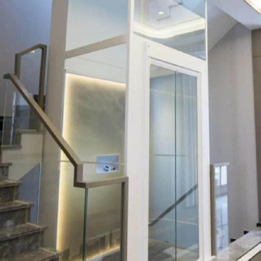
Aluminium-Cabin Hydraulic Home Elevator – 14.5 m, 5 Stops, Single-Phase
Product Details:
Brand Name
YIMEISITE
Place of Origin
China
Payment & Shipping Terms:
Minimum Order Quantity
1 set
Price
USD 4,000-10,000 per set
Payment Terms
T/T,L/C
Supply Ability
20 sets per month
Delivery Time
45 working days
Packaging Details
Export non-fumigation wood box
| Safety Features: | Emergency Stop Button | Power Supply: | Single-phase AC |
| Number Of Stops: | 5 | Large Cylinders: | 2.9 Meter Length |
| Pit Depth: | 0 M | Floor: | Deck Floor |
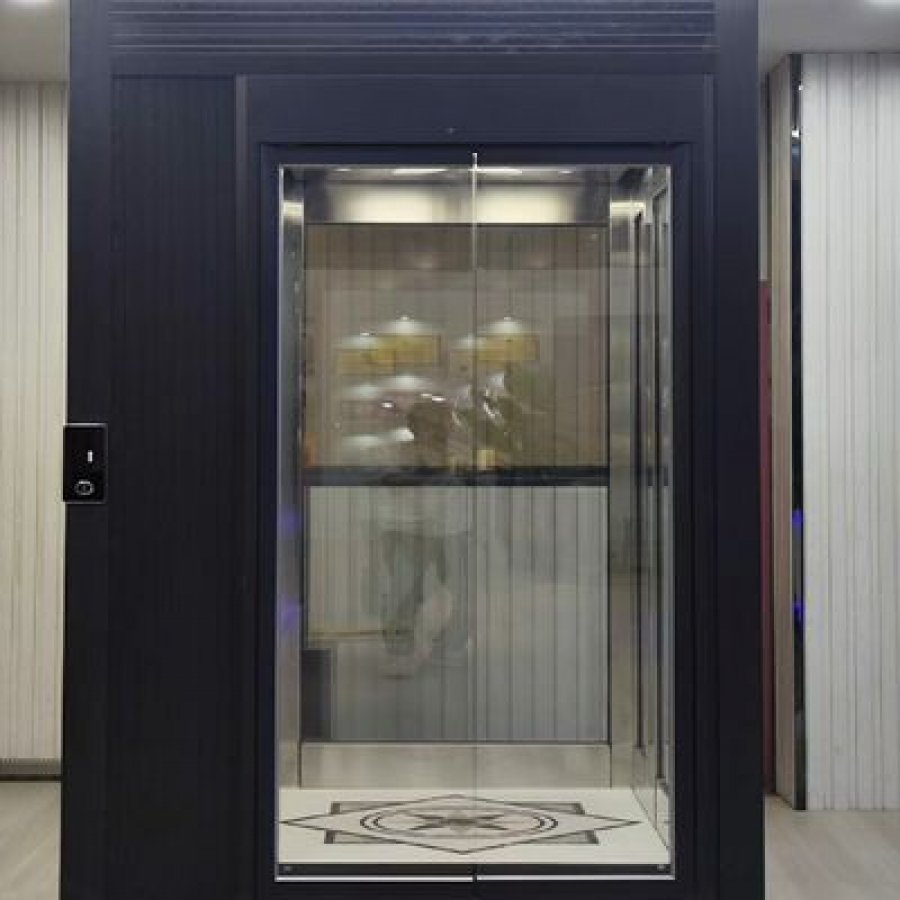
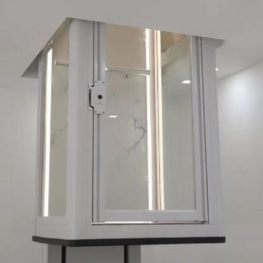
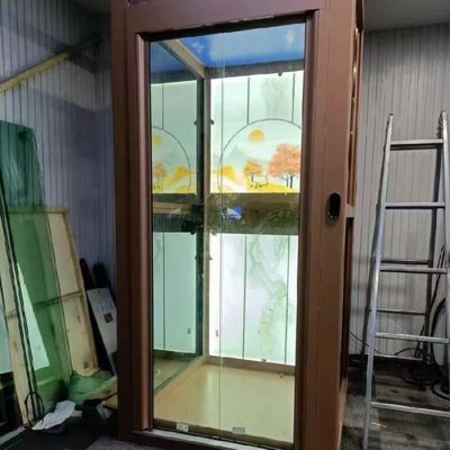
| Door Type: | Automatic | Cabin: | 304# Stainless Steel/aluminium Alloy |
| Highlight: | aluminium alloy cabin elevator,automatic home elevator,automatic cabin elevator | ||
Product Description
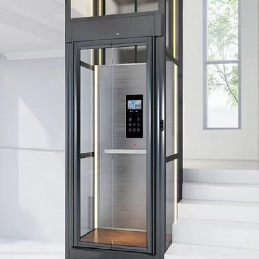
Aluminium-alloy cabin · hydraulic drive · 5 stops · 14.5 m travel · 0 m pit · single-phase 220 V
An aluminium cabin is chosen for the weight it saves and the shape it allows. Everything else on this page follows that decision.
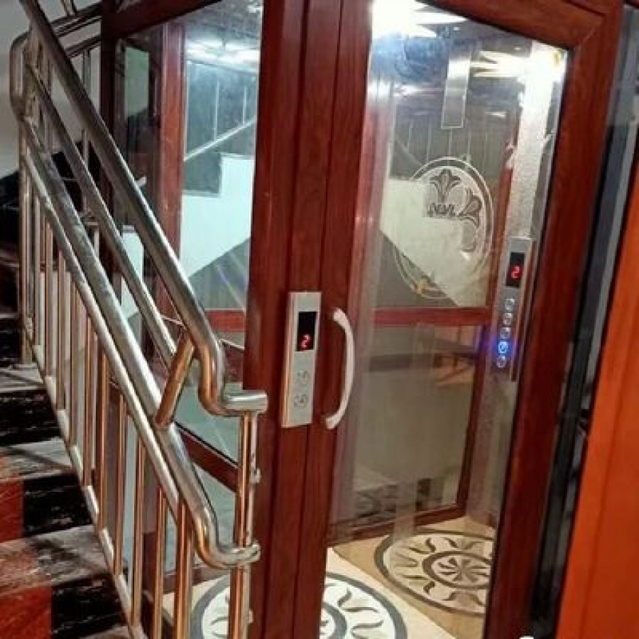
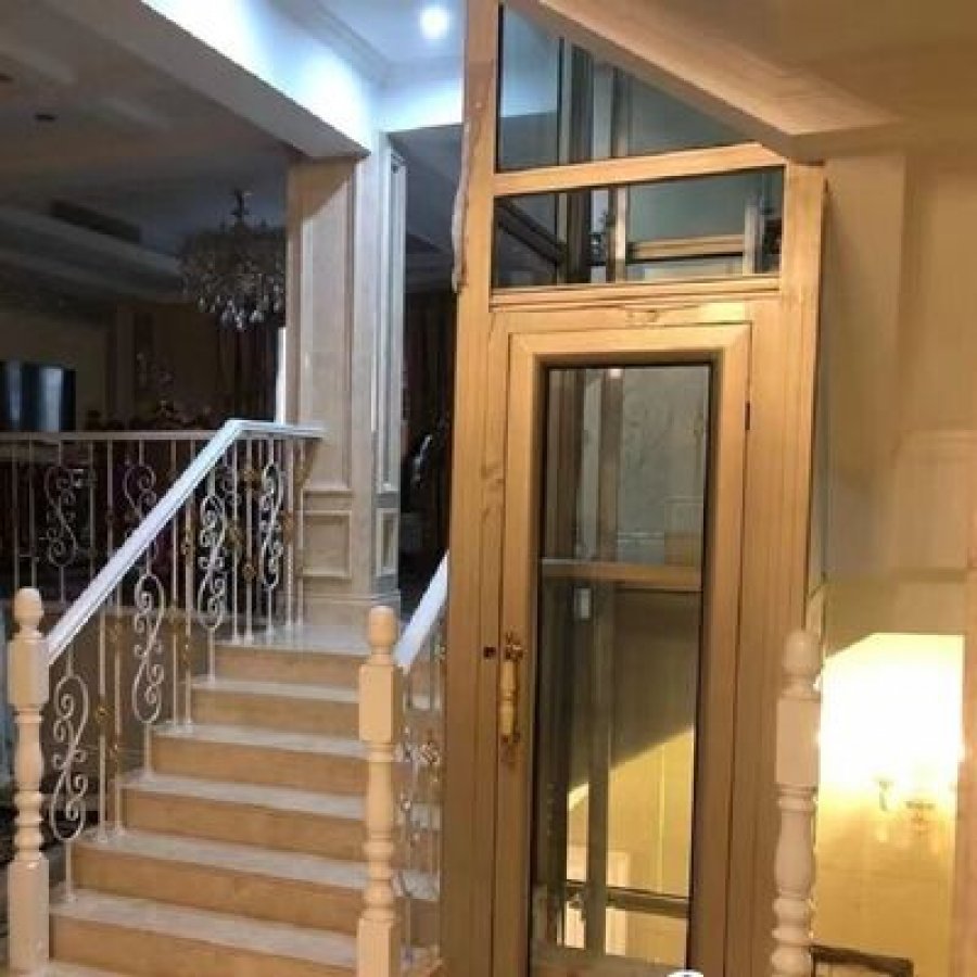
This page covers a cabin hydraulic home elevator built with a 304 stainless steel or aluminium-alloy cabin. It is quoted with an automatic door, up to 5 stops, a travel of 14.5 m, a 0 m pit and 3 m of clearance above the top landing, driven by 2.9 m hydraulic cylinders on a 4.7 kW unit at 220 V single-phase.
Aluminium is lighter, which matters when the structure carrying the lift was not designed for a lift; stainless steel is heavier and harder, which matters where the cabin is expected to take knocks. Both are offered on this model, so the question is not which is better in general but which suits the house — and the answer is settled before the order rather than after it.
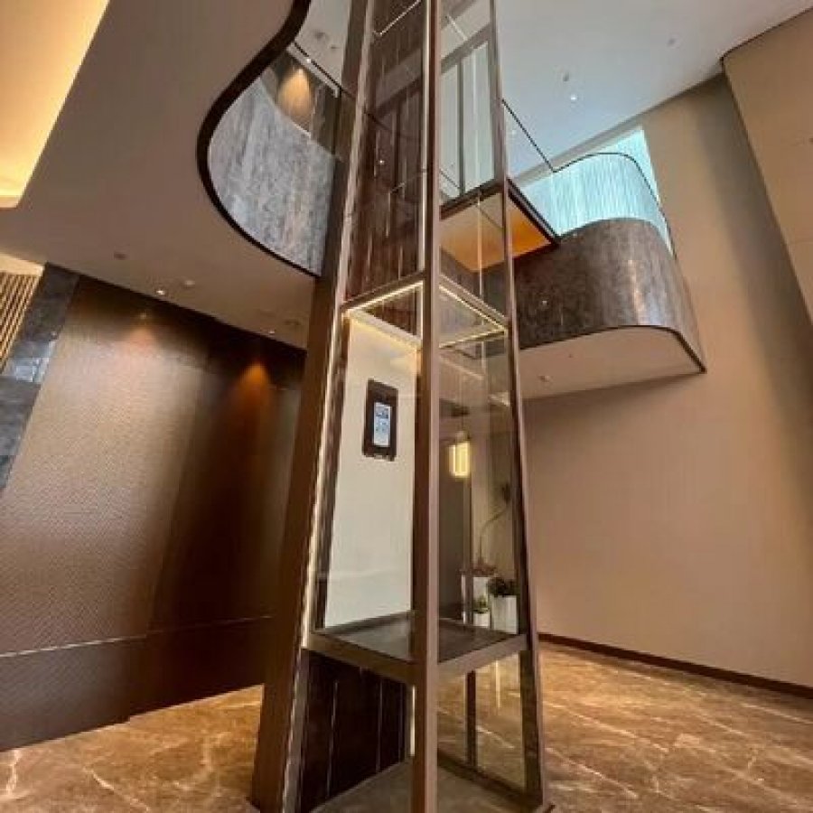
Two things shape it: what the building can carry at the top of the run and around the shaft, and what the cabin should look like in a stairwell, a hall or beside a glass wall. A hydraulic drive on single-phase power then removes the constraint that usually decides the machine, which is the electrical supply.
What this model is quoted with
The specification block for this model records 5 stops, a 0 m pit, a floor arrangement listed as a deck floor, an automatic door, and a cabin in 304# stainless steel or aluminium alloy. It names one safety device, an emergency stop button, and one supply condition, single-phase AC. The machine is driven by 2.9 m hydraulic cylinders on a 4.7 kW unit, with microprocessor-based control, at 220 V, 50 Hz. Travel is quoted to 14.5 m, with 3 m of clearance above the top landing.
Two things are deliberately absent from that list, and they are absent for the same reason: nothing on this page invents them. The block does not quote a rated load, so no load figure appears here — the load your lift is rated for is fixed at order and set on the nameplate of the unit that ships. The block also carries no certification line, so this page claims no certification. Both omissions are checkable in the specification block on this page, and both are answered the same way if they matter to your project: Contact our engineers.
Fit check: three questions, three outcomes
Three answers settle whether this machine suits the house at all. Each one is cheap to check before the shaft is built and expensive to discover afterwards.
1 Does the lift have to serve up to five landing positions within 14.5 m of travel?
2 Is the structure at the shaft and at the top landing able to carry the cabin, the guide rails and the hydraulic cylinders?
3 Is there a single-phase 220 V supply at the shaft for a 4.7 kW unit, or room in the existing distribution board for one?
All three answers are yes — this is the right class of machine
A cabin hydraulic home elevator suits a house of up to five landing positions inside 14.5 m of travel, with a shaft that can carry a hydraulic installation and a wall that can take a single-phase supply. What remains is dimensional and decorative: cabin size, door positions, the material and finish of the cabin, and whether the shaft is enclosed or glazed. All of it is settled on a drawing before anything is cut.
Three measurements decide this one
This is where most enquiries land: the shape of the project is right, but three figures are still assumptions. Count the landing positions, measure floor to floor from the lowest to the highest, and ask an electrician to confirm what is actually available at the shaft. The three questions come back on the printable survey sheet at the end of this page, so they can be answered with a tape measure rather than from memory.
This machine is probably not the answer — check the alternatives
A travel beyond 14.5 m, more than five landing positions, or a supply that is fixed at three-phase only moves the project outside this model's quoted arrangement, and stretching the quotation is the wrong fix. A house with two or three stops may also be served more cheaply by a smaller machine. The material comparison and the drive explanation below set out where the boundaries sit, and the alternatives are worth pricing before the shaft is built rather than after.
The result changes as you answer. Nothing on this page is sent anywhere, and the answers are yours to keep for the survey sheet.
Aluminium-alloy cabin or 304 stainless cabin: what actually differs
The specification block for this model gives one cabin line: 304# stainless steel or aluminium alloy. Two materials, one lift, and a decision that is usually made on appearance and then justified on structure. It is worth separating the two, because only one of them is reversible after the lift is running.
Why aluminium-alloy cabins are specified
Aluminium-alloy cabin frames are chosen for mass. For a given frame section, an aluminium profile is substantially lighter than the same profile in steel. That is why it appears so often in retrofit work: the shaft, the floor opening and the top-landing structure are already built, and the lift has to fit what is there rather than the other way round. An aluminium cabin home lift is therefore the natural answer in an infill shaft. What aluminium does not do is harden the cabin: the panel is softer than stainless, so a trolley corner leaves a mark where steel would have shrugged it off.
Why 304 stainless cabins are specified
A 304 stainless cabin is the opposite trade. It is heavier, and that weight is paid for at the structure rather than in the cabin. In return the surface is hard, the finish holds its appearance in ordinary residential use, and brushing out a scuff is standard practice for a metal fabricator. Stainless is also the conventional answer where the lift is inserted into an existing stairwell of plaster, stone or timber, because a brushed panel sits quietly beside those materials. In a glazed shaft it reads differently again: the cabin reflects rather than disappears.
| Decision point | Aluminium-alloy cabin | 304 stainless cabin |
|---|---|---|
| Mass carried by the building | Lower, because the frame and panels are lighter for the same section. This is why it appears most often on retrofit and infill projects | Higher, and paid for at the shaft and the top-landing structure rather than in the cabin |
| Surface hardness | Softer: an impact leaves a visible mark more easily, and deep marks are difficult to remove | Hard: brushing out light scuffs is routine fabricator work |
| How it reads in daylight | Matte, cooler and visually lighter; a coated finish can be matched to joinery | Brushed or mirror: reflective, and it reads as metal rather than as a painted panel |
| Cleaning in normal use | A coated surface wipes down like painted metal; unfinished sections need more care | Resists everyday marking, but a mirror finish records fingerprints and shows the direction of the wipe |
| Contact with other metals | Fixings and rail brackets need their own detail, so dissimilar-metal contact is designed out | The more conventional pairing against steel fixings and rail steel |
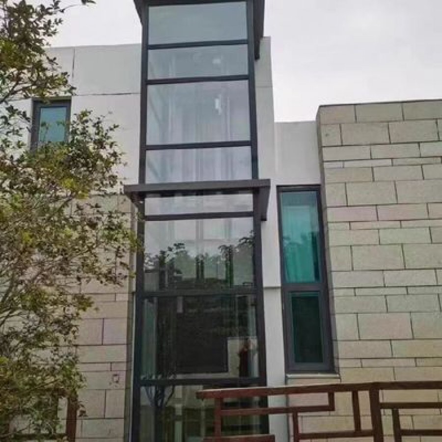
| In a glazed or open shaft | Slim sections make the cabin look lighter, which suits a glass shaft in a small stairwell | A denser, more solid presence; better where the cabin is the feature rather than the shaft |
| What it cannot change | Stops, travel, pit depth, overhead clearance and the hydraulic drive all stay as recorded | The same figures stay as recorded; the cabin is a load, not a rating |
| What to settle before ordering | Frame section, panel thickness, finish colour and the fixing detail against the guide rails | Panel thickness, brush or mirror direction, and the structural check at the top landing |
One practical note sits behind that table. In retrofit work the cabin material is often decided by a structural figure that arrives late. That is why the survey sheet asks for the shaft plan and the floor construction, as well as for dimensions.
If the cabin is the deciding factor and the house has the structure for the heavier option, the 304 stainless steel cabin version of the same 14.5 m five-stop arrangement is the direct comparison. Both pages read from a specification block rather than from a brochure, so the two can be compared line by line.
How a hydraulic cabin lift actually moves, and why the cylinders are 2.9 m
A hydraulic home lift does not pull the car up. It pushes it. A power unit at the base of the shaft drives hydraulic oil into cylinders, the cylinders extend, and the car rises with them. Coming down is the same circuit in reverse: the car descends under its own weight while a valve controls how fast the oil is allowed back to the tank. That single difference from a traction drive is what makes the rest of this specification possible.
Because the lifting force is generated at the bottom of the run, the heavy parts stay at floor level. There is no machine above the shaft and no counterweight travelling beside the car, so the top of the run carries the car and its guide rails alone. In a house where the shaft passes through an existing floor and nothing above it was designed to be loaded, that is usually the decisive advantage.
Why the block records 2.9 m cylinders
The block records 2.9 m large cylinders, and that figure deserves a plain explanation because it is often read as a travel limit. It is not: cylinder length describes the hardware that carries the load, and it interacts with the pit arrangement and where the power unit can sit. This model is quoted with a 0 m pit, so the bottom of the installation cannot be sunk below floor level. The cylinder base, the load-bearing detail around it and the route for the oil line are all resolved at the level that already exists. Settled after the floor opening is formed, that constraint turns into a concrete-pouring mistake.
Overhead clearance 3 m
The block quotes 3 m of clearance above the top landing. It is a building measurement, taken where the car, its rails and its sheave arrangement will sit, and it cannot be improvised on site. A roof or a ceiling lower than the quoted figure is a redesign, not an adjustment.
Power unit
A 4.7 kW unit on a 220 V single-phase supply drives the oil circuit. It needs somewhere to stand with service access, and it is normally placed so that the oil line run to the cylinders is short and protected.
Cylinders
The block records 2.9 m large cylinders. With a 0 m pit the cylinder base sits at floor level, so the base detail and the oil line route are fixed by the floor construction rather than by how deep a pit could be dug.
What the drive means in daily use
The car leaves and arrives on a hydraulic valve rather than a rotating machine, so the noise in the house comes from the power unit and the oil circuit rather than from a machine room above the top landing. Levelling at each stop is set during commissioning, and the microprocessor-based control recorded in the block handles the call sequence, the door operator and the stop positions. Where the lift passes beside a bedroom, the practical question is therefore where the power unit stands. Because the load path is vertical, the guide rails take their share of the running load along their whole length, which is why the rail fixing detail appears on the survey sheet.
Tip: hover or tap the three markers in the section drawing. The same figures are repeated in the specification table and again on the printable survey sheet.
The specification, read line by line
The table below is the specification block for this model, with metric figures and their imperial equivalents in the same cell. The switch above the comparison table changes both tables at once, and the converter below covers the two figures that decide most site surveys: the travel and the clearance above the top landing.
| Item | Recorded value | What it decides |
|---|---|---|
| Product type | Cabin hydraulic home elevator | A push-from-below drive with no machine above the shaft |
| Travel | 14.5 m47.6 ft | The tallest run this model is quoted for, lowest landing to highest |
| Stops | 5 | Landing positions served, counted from the lowest to the highest |
| Pit depth | 0 m0 ft | Whether the floor has to be excavated at the bottom landing |
| Overhead clearance | 3 m9.8 ft | The clear height needed above the top landing |
| Drive | Hydraulic, 2.9 m large cylinders | Where the load is generated and where the oil circuit runs |
| Cabin | 304# stainless steel or aluminium alloy | Mass at the shaft and the surface the household sees |
| Door type | Automatic | Landing doors that open and close with the car rather than by hand |
| Floor arrangement | Deck floor | The floor construction at the lowest landing, which the block records as a deck floor |
| Power supply | 220 V, 50 Hz, single-phase | Whether an existing domestic supply can serve the lift |
| Motor power | 4.7 kW | The circuit and protection the power unit needs at the shaft |
| Control | Microprocessor-based | Call sequence, stop positions and door timing |
| Safety device recorded | Emergency stop button | The device the block names, in addition to the devices the control circuit includes |
Three lines in that table change a quotation rather than a drawing. Pit depth 0 m means the bottom landing is not excavated, so the base detail is part of the design. Travel 14.5 m is a ceiling on the run, not an average: read as a hydraulic lift for 5 storey house projects, the two figures to check are the total travel and the clear height above the top landing. And 220 V single-phase is what makes the model usable where no three-phase supply exists, which is also why the 4.7 kW figure is worth checking against the existing board.
Two values are missing from the table, and the omission is deliberate. There is no rated load figure, because the block does not quote one; the load your lift is rated for is agreed at order and set on the nameplate of the unit that ships. There is no certification line, because the block carries none, so this page claims none. Both gaps are answered with the same sentence: Contact our engineers.
Convert a measurement before you send it
Two figures are worth converting before a survey: 3 m of overhead clearance, which is 3,000 mm or about 9.8 ft, and 14.5 m of travel, which is 14,500 mm or about 47.6 ft.
0 m pit and 3 m overhead: the two building measurements that decide the order
Most home lift projects are settled or lost on two numbers, and this model states both of them: a pit depth of 0 m and an overhead clearance of 3 m. One is a saving, the other is a demand. Read together, they describe the building this lift is designed to fit.
A 0 m pit does not mean that nothing happens under the car. It means the floor is not excavated to create a pit: the arrangement is resolved at the finished floor level, with the cylinder base and its load-bearing detail sitting where the floor already is. That is what makes the model usable in an existing house, where breaking out a floor slab is the most disruptive part of a lift installation. It also removes the drainage question a sunken pit brings with it, and what replaces the pit is a base detail designed for the floor construction actually present.
The 3 m of overhead clearance
The 3 m overhead clearance is the opposite kind of figure: a minimum clear height above the top landing, measured where the car, its guide rails and the sheave arrangement stand at the end of the run. A roof structure or landing trim that leaves less is not a detail to be trimmed on site; it changes the arrangement. This is the measurement to take first when a shaft runs up through a roof space.
This arrangement suits
- Existing floors left intact — nothing is excavated below the finished level
- Retrofit and infill shafts — a drive with no machine above the top landing
- Households that cannot tolerate a wet trades pit — no sump, no tanking, no pump
- Up to five landing positions inside a 14.5 m run
- A single-phase household supply rather than a three-phase service
Check before you order
- Clear height above the top landing — the quoted figure is 3 m and it is a minimum
- The substrate the guide rails fix to over the whole run, top to bottom
- The floor construction at the lowest landing, where the base detail is resolved
- How the cylinder and the cabin reach the shaft during installation
- Where the power unit stands, with service access left clear
The sequence matters as much as the values. Rail fixing comes before the shaft lining is closed, the base detail before the floor finish is laid, and the power unit position has to be decided while the oil line route is still open. A house that is finished before the survey is a house with a more expensive installation, which is why this page asks for measurements early rather than a deposit early.
Where the constraints do not fit, the answer is usually a different arrangement rather than a modified one. The five-stop pitless hydraulic home elevator covers the same 0 m pit principle in a different travel and stop combination, and the hydraulic home elevator range sets out the other specifications in the same family.
Cabin, door and finish: the parts a household touches
The specification block records a cabin in 304# stainless steel or aluminium alloy and a door type of automatic. Everything the household experiences day to day sits inside those two lines: the panel it sees, the surface it brushes past, and a door that opens without being pushed.
An automatic door changes the rhythm of the lift more than any other option on this page. There is no gate to lift and no panel to slide by hand, so the sequence at each landing is the same for a child, a visitor and someone carrying shopping. The door operator works with the microprocessor-based control recorded in the block, which sequences the car door and the landing door together and holds the open time while someone steps through. In a house where the lift is used by people who find stairs difficult, that is what matters in daily use; the cabin material is what matters in ten years.
What the automatic door removes
Manual gates and folding panels need a hand free and a remembered habit. An automatic door removes both, and removes the half-open landing that a hand-operated gate is left in when a household is in a hurry.
What it adds to the design
A door operator needs clearance at each landing, a sill detail that copes with the floor finish, and a fixing that suits the wall it sits in. All three are drawing items, and all three are cheaper to resolve before the landing walls are finished.
What stays a project decision
Clear opening width, handing, sill material and whether the cabin panels are solid or glazed are set per project. The block records the door type; it does not record a width, so this page does not invent one.
Inside the cabin, the comparison table above sets out where each material is the better answer. The part usually overlooked is that a cabin interior is judged from the inside, in artificial light, at the end of a day. A brushed stainless finish reads cooler and hides handling marks better. An aluminium panel with a coated finish can be matched to the joinery in the hall, which is often what makes a lift look like part of the house rather than an addition to it.
Two details are worth fixing early because both are awkward later. The sill has to reconcile the landing floor finish with the car floor, so the finish material is chosen before the sill is made. A handrail position, where one is wanted, is a factory item on the panel rather than something added on site.
The two panels in the drawing above open on a loop, in the sequence the operator runs them: car door first, then the landing panel, with the hold time set at commissioning.
Running it on a household single-phase supply
The block records 220 V, 50 Hz, single-phase for a 4.7 kW power unit. For a house, that is the line that decides whether the lift is a small electrical job or a supply upgrade, because a single-phase lift of this size does not ask the property to be reconnected to three phases.
The practical consequence removes the objection that appears in most home lift conversations: a household that already has a single-phase service can be surveyed for this model without changing the incoming supply. What still has to be confirmed is the capacity left in the existing distribution board, the route for a dedicated circuit to the shaft, and where the power unit can stand with access left clear for servicing. None of those three is a lift decision; all three are settled by an electrician before the order.
The number to give an electrician is the one in the block: 4.7 kW at 220 V single-phase. Circuit rating, protection type, cable size and the earth-fault arrangement are theirs to size against local practice. What this page can do is state the load the lift presents and where it has to arrive.
Supply that works as it stands
- 220 V single-phase already installed at the property — the condition the block records
- Spare capacity in the board for a dedicated circuit to the shaft
- A route for that circuit that can be run before the walls are closed
- A position for the power unit with clearance for service access
- An electrician's sign-off on protection and earthing, before installation starts
Where the plan changes
- No spare way in the board — a distribution change rather than a lift change
- A supply that is not 220 V at the property — confirm what is actually there rather than what is assumed
- A power unit boxed into a finished room — access for servicing becomes a joinery problem
- An oil line run through a finished space — the route is designed, not improvised
- Generation or a UPS other than the household supply — raised with the engineers, not resolved on site
Two further points belong with the electrical work. The power unit needs somewhere to stand that a service engineer can reach, and the oil circuit needs a protected route; both are cheaper before the room is finished than after. And a single-phase installation usually means the lift can be added to an existing house without involving the utility at all.
If the supply at the property is not the one recorded in the block, that is a question for the engineers rather than a reason to change the order quietly: Contact our engineers.
Safety devices and acceptance: what the block names, and what has to be confirmed
The specification block for this model names one safety device: an emergency stop button. That is a narrow statement, and it is written that way on purpose. A home lift's protective arrangements depend on the door type, the drive and the control circuit fitted to the unit. A page that lists devices it cannot point to in the specification is worth less than a page that says which questions to settle in writing.
So the checklist below is a list of questions rather than a list of claims. Take it to the quotation stage, get each answer in writing, and the acceptance list at handover writes itself. Two items matter more than the rest in a house. The emergency stop button has to be reachable by the people who actually use the lift. And the arrangement that governs what the lift does when the supply fails mid-run has to be known before commissioning rather than discovered in the first power cut.
Safety questions to settle in writing before the order
Settled so far: 0 of 8
Why written answers matter here
Safety arrangements are the part of a lift quotation that is easiest to leave vague and hardest to add later. A door interlock arrangement, for example, is designed into the landing door and the control cabinet together; it is not a component that can be posted out and fitted to a finished installation. The same applies to anything that governs behaviour during a power failure, because it is a control-circuit decision.
Acceptance is the other half of the same process. At handover the useful test is not a demonstration of the lift running — every lift does that — but a walk through the eight items above, with the installer showing where each arrangement sits.
The control side of the lift is covered in more detail on the control and safety arrangements page, which walks through the same questions from the point of view of the operating circuit.
From survey to handover: the sequence, and what happens in each step
A hydraulic home lift is installed in a fixed order, and the order is what protects the project. Each step below produces something the next one needs, which is why the survey answers come before the order rather than after it, and why the base detail is settled before the floor finish is laid.
-
1. Survey and drawing set
Measure the two figures this model is built around — clear height above the top landing and total travel. Then record the floor construction at the lowest landing, the wall material behind the guide rails, the position available for the power unit and the supply at the shaft. The output is a drawing set, not a set of notes: shaft plan, section, door positions and the base detail that replaces the pit.
-
2. Order and confirmation
The cabin material, the finish, the door handing and the sill detail are confirmed here, with the commercial terms. The minimum order quantity is one set, payment is by T/T or L/C, and manufacturing is quoted at 45 working days. Supply is quoted at around 20 sets per month, so a project with a fixed opening date should be placed against that figure rather than against hope.
-
3. Manufacture and pre-assembly
Cabin panels, guide rails, the hydraulic cylinders and the power unit are produced to the drawing set and tried together before dispatch, which is the stage where a surprise is still cheap.
-
4. Packing and dispatch
The lift ships in export non-fumigation wood boxes, packed so that the items arriving first are the ones needed first on site.
-
5. Site installation
The base detail is completed at the lowest landing, the guide rails are fixed along the run, the cylinders and the power unit are set, and the car and landing doors follow. Electrical work, the oil circuit and the door operator are then connected and checked before anything is closed up. Because there is no machine above the shaft, the heavy work stays at floor level.
-
6. Commissioning and handover
Stop positions, levelling at each landing and door timing are set, and the eight safety questions above are answered face to face with the household. The documents handed over should include the arrangement drawings, the commissioning records and the upkeep schedule.
Two timings to plan around
Two timings are worth planning around rather than discovering. The electrical circuit to the shaft should be run while the walls are still open. And the cabin and cylinder delivery should be timed against the state of the shaft, because a hydraulic installation that arrives before the base detail is ready simply stands in a hallway.
Where the survey produces a measurement this model cannot meet, the answer is a different arrangement in the same family, not a modified installation. That covers three cases: more than 14.5 m of travel, more than five landing positions, and less than 3 m of clear height above the top landing.
Upkeep: the short list that keeps a hydraulic lift predictable
Upkeep on this lift is not a long list, but it is a specific one, and its centre of gravity is different from a traction machine. There is no gearbox and no machine above the shaft to service; instead the items that matter are the hydraulic circuit, the door operator and the control, and all three are reached at floor level.
The hydraulic circuit
Oil is a consumable, not a permanent component. Level, condition and the state of the cylinder seals are what a service visit checks, and the position of the power unit is what makes those checks quick. A unit boxed in behind finished joinery turns a ten-minute inspection into a joinery job.
Doors and operator
An automatic door works hardest, because it runs at every stop. Sill condition, panel alignment and the operator's travel and hold time are the items to watch, and a door that hesitates is a signal to have it adjusted rather than to live with it.
Control, stops and devices
Levelling at each landing, stop positions and the devices listed on the safety questions belong in the same visit: testing the emergency stop button and the landing door arrangements is routine upkeep, not something to leave until a fault appears.
What this page cannot tell you about upkeep
The specification block for this model records no warranty line and no service interval, so neither is claimed here. Three things are worth asking before the order. What upkeep schedule applies to the lift you order, what warranty terms come with it, and which service partner will look after it in your country.
Two habits that keep upkeep simple
Two habits make the rest straightforward. Keep the power unit position clear of stored items, because access decides whether a service visit is half an hour or half a day. And keep the handover documents with the lift rather than in a folder of household paperwork, so the next person to work on it starts from the arrangement drawings rather than from a guess.
Questions buyers ask before ordering this model
Ten questions that come up in almost every enquiry for a cabin hydraulic home elevator, answered from this page's own specification block rather than from a brochure.
What exactly is a cabin hydraulic home elevator?
It is a home lift with a car in an enclosed cabin and a hydraulic drive: a power unit drives oil into cylinders, which push the car up, and the same circuit controls its descent. This model is quoted for up to 5 stops and 14.5 m of travel, with a cabin in 304# stainless steel or aluminium alloy.
Aluminium-alloy cabin or 304 stainless cabin — which one should I choose?
Choose by what the building and the room need rather than by a general rule. The aluminium-alloy cabin is lighter, which helps when the shaft, the floor opening or the structure above it is already built. The 304 stainless cabin is heavier and harder, which suits an interior that has to take knocks and still look the same in ten years. The comparison table above sets the two side by side; the structural check at the shaft turns the preference into a decision.
Does a lighter cabin mean a lower payload?
No. The cabin material changes the load the structure carries, not the rating of the machine. This page quotes no load figure, because the block records none: the rated load is agreed at order and set on the nameplate of the unit that ships.
Does a 0 m pit mean nothing at all happens below the floor?
It means the floor is not excavated to form a pit. There is still a base arrangement at the lowest landing, where the cylinder base and its load-bearing detail sit against the floor construction that already exists, and the oil line route has to be resolved at that level. What a 0 m pit removes is the excavation, the tanking and the drainage that a sunken pit brings with it.
How do I check whether I have the 3 m of overhead clearance?
Measure clear height above the top landing, from the landing floor to the lowest obstruction above it, wherever the car, its guide rails and the sheave arrangement will stand at the end of the run. The quoted figure is 3 m, or about 9.8 ft, and it is a minimum. A roof space, a landing trim or a ceiling that leaves less than that changes the arrangement rather than being trimmed on site.
Will it run on the house's existing single-phase supply?
The block records 220 V, 50 Hz, single-phase for a 4.7 kW power unit, so a property that already has a single-phase service of that kind does not need reconnecting to three phases. What still has to be confirmed is spare capacity in the distribution board, a route for the dedicated circuit, and a position for the power unit with service access. Give an electrician the 4.7 kW figure and let them size the circuit.
What are the drawbacks of a hydraulic drive in a house?
Three, and they are worth knowing before you commit. Hydraulic oil is a consumable that has to be checked and eventually replaced, so the power unit needs to stay accessible. The unit occupies floor space at the base of the run, which a machine room less traction lift would not. And this model's quoted ceiling is 14.5 m of travel and 5 stops, so a taller run is a different arrangement rather than a longer version of this one.
How much does a lift like this cost?
This page does not quote a price, because the amount depends on the travel, the cabin material and finish, the door arrangement, the destination and the terms of the order. A figure for your project is prepared against your measurements and drawings, which is why the survey sheet below asks for measurements rather than for a budget.
How many floors can it serve?
The block records 5 stops within a travel of 14.5 m. Five stops is a count of landing positions, not of storeys, so a split level uses them up quickly. Measure total travel from the lowest landing floor to the highest rather than adding up room heights, because that is the figure the specification is written against.
Is there a warranty, and who looks after it once it is running?
The specification block carries no warranty line and no service interval, so this page claims neither. The warranty terms that apply, the upkeep schedule and the service partner in your country are agreed at order and handed over with the documents — ask for them in writing, together with the eight safety arrangements listed above.
What to send, and what comes back
An enquiry for this model does not need a specification document, only the measurements the arrangement already depends on and a sentence about the house. The list below is ordered so that the drawing set can start from your reply rather than from a second round of questions.
Ten items that make a usable enquiry
Ready to send: 0 of 10
Printable survey sheet
The same measurements, on one sheet, for the person standing in the house with a tape measure. Print it, work through it, and the answers become the enquiry rather than notes to be written up afterwards.
Home lift survey — ten measurements
Measured so far: 0 of 10
The tick boxes work on the page and stay in your browser.
If a measurement cannot be taken yet, write it down as it stands. A shaft in an unusual wall or a landing shared with a staircase is better as a stated gap than as a filled-in guess, because each one changes a drawing rather than a price list.
Send the travel, the headroom and the supply
Three measurements are enough to start. We will check them against the 14.5 m travel, the 5 stops, the 0 m pit and the single-phase supply.
Want to Know more details about this product
Similar Products