 English
 Español
Categories
Contacts
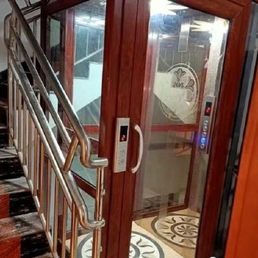
Automatic Door Hydraulic Home Elevator with Emergency Stop
Product Details:
Brand Name
YIMEISITE
Place of Origin
China
Payment & Shipping Terms:
Minimum Order Quantity
1 set
Price
USD 4,000-10,000 per set
Payment Terms
T/T,L/C
Supply Ability
20 sets per month
Delivery Time
45 working days
Packaging Details
Export non-fumigation wood box
| Safety Features: | Emergency Stop Button | Motor: | 4.7 Kw |
| Power: | 220V, 50Hz, Single Phase | Control System: | Microprocessor |
| Pit Depth: | 0 M | Number Of Stops: | 5 |
| Large Cylinders: | 2.9 Meter Length | Cabin: | 304# Stainless Steel/aluminium Alloy |
| Highlight: | automatic hydraulic home elevator,automatic hydraulic home elevators,emergency stop hydraulic home elevator | ||
Product Description
Hydraulic home elevator · automatic doors · 5 stops · 14.5 m travel · 0 m pit · emergency stop
The automatic door is the part of a home lift your household touches twice a day
This page covers an automatic door hydraulic home elevator with an emergency stop button and 5 stops over up to 14.5 m of travel. It is quoted with a 0 m pit, 3 m of overhead clearance, a 4.7 kW motor on a 220 V, 50 Hz single phase supply, microprocessor control and a 304 stainless steel or aluminium alloy cabin.
Most pages about a hydraulic home lift explain the pump. The more useful question for a family is smaller: who has to open the door, and what happens when someone cannot. An automatic landing door answers a specific set of problems: a wheelchair, a walking frame, a parent carrying a child, an elderly owner who should not be leaning through a doorway to reach a control panel. It also costs something — one more machine to maintain, and stricter installation conditions.
This page works through both halves. It covers what an automatic door changes in daily use, and what the 0 m pit and 3 m clearance mean on a real site. It also covers how a single phase supply feeds a 4.7 kW drive, and what has to be checked before handover.
The machine this page describes
The specification block for this model lists a hydraulic drive, automatic door operation, 5 stops over a quoted maximum travel of 14.5 m, a pit depth of 0 m and overhead clearance of 3 m. The motor is quoted at 4.7 kW on a 220 V, 50 Hz single phase supply, and the control system is a microprocessor unit. The cabin is offered in 304 stainless steel or aluminium alloy, the cylinders are quoted at 2.9 m, and the safety device named in the block is an emergency stop button. Warranty is 1 year, in an export non-fumigation wood box.
Two of those figures do the heavy lifting on a residential project. The 0 m pit removes excavation from the schedule and the single phase supply removes the need for a three-phase connection — both are conditions that either fit the house or do not.
Fit check: three questions, three outcomes
Three answers decide whether this class of machine suits the house at all. Each one is cheap to check and expensive to discover afterwards.
1 Does the lift need to serve no more than five landings, with a travel inside 14.5 m?
2 Can the shaft work with a 0 m pit, and is 3 m of overhead clearance available above the top landing?
3 Is a single phase 220 V, 50 Hz supply available at the shaft for a 4.7 kW motor, with room for the control panel?
All three answers are yes — this is the right class of machine
A hydraulic home elevator with automatic doors and a 0 m pit suits a house of up to five levels with a single phase supply at the shaft. What remains is dimensional: cabin size, landing door positions, cabin material and where the power unit stands, all settled on a drawing before anything is manufactured.
Three measurements decide this one
This is where most enquiries land: the shape of the project is right but three figures are still assumptions. Count the landings, measure floor to floor between the lowest and the highest, and confirm the supply with an electrician rather than from memory. The same three questions reappear on the printable sheet at the end of this page.
This machine is probably not the answer — check the alternatives
Six or more landings, a travel beyond 14.5 m or a three-phase-only supply sit outside this model's quoted figures, and a home that cannot spare 3 m above the top landing needs that answer before a lift is chosen rather than after. Send the site details and we will say which applies.
The result changes as you answer. Nothing on this page is sent anywhere, and the answers are yours to keep for the survey sheet.
Automatic doors against manual landing doors: what actually changes
Both arrangements lift the same cabin between the same floors. The difference sits entirely at the threshold, in the two seconds before and after the ride, which is where a residential lift is judged. A hydraulic home lift with automatic door operation takes the opening and closing away from the passenger; a manual landing door leaves it in their hands.
The comparison below is not an argument that one is better. It is a list of the places where the two behave differently, so the choice can be made against the household rather than against a photograph.
Where an automatic door earns its place
- Both hands full. Shopping, a child, a laundry basket or a tray of food does not have to be put down to travel.
- Wheels. A wheelchair, a walking frame, a rollator or a pram meets a door that is already open rather than a handle that has to be reached and pulled.
- Reach and grip. For an owner whose hands or shoulders are weakening, the door stops being the hardest part of the journey.
- An even threshold. Nothing is left ajar, so nothing is left to be pushed shut behind the cabin.
Where it costs something
- One more machine. The door is driven by its own operator, and an operator is a wearing part with a maintenance interval of its own.
- Stricter conditions. The landing opening and the space around it have to suit the door drive, and that has to be settled at the drawing stage.
- Behaviour without power. What happens at the threshold during a supply failure is a question to have answered in writing for your installation rather than assumed from a brochure.
| Question | Automatic landing door | Manual landing door |
|---|---|---|
| Who opens it | The door is opened by its own drive as part of the journey | The passenger opens it, by hand or by a handle, at every landing |
| Arriving with both hands occupied | Nothing needs to be set down | Load has to be put down to work the door |
| Wheelchair, frame or pram | The clear opening is presented by the drive | The user holds the door while manoeuvring through the opening |
| Children travelling with an adult | One less lever within reach at floor level | A door that can be worked by hand is also a door that can be worked by a child |
| Extremes of temperature and draught | Closes itself after each run | Depends on whether the last user closed it |
| Maintenance attention | The operator and its travel are part of the service visit | Fewer driven parts; hinges and catches instead |
| What has to be fixed early | Opening width and the space at each landing for the door drive | Opening width and the swing or slide space kept clear of furniture |
Read as a whole, the table says something simple: an automatic door moves work from the passenger to the machine. On a lift used twice a day by an able-bodied owner that trade is close to neutral; on a lift installed because someone has stopped managing stairs, it is usually the point of the installation.
Door operator
The drive that opens and closes the landing door as part of the run instead of the passenger doing it. On this model the landing doors are automatic; opening width, panel handing and the space reserved for the operator are fixed per project on the approval drawing.
The eleven figures that decide whether this lift fits the house
A specification list is only useful read as a set of conditions. The figures below have to survive contact with the building. They cover the travel available for the number of floors, the two dimensions that govern how much structure the lift needs, the supply the motor asks for, and the parts that decide how the ride feels.
| What the figure covers | Value quoted for this model | Why it matters on site |
|---|---|---|
| Lift type | Pitless hydraulic home elevatorPitless hydraulic home elevator | Sets the whole installation shape: hydraulic drive, no excavation for the lowest landing |
| Maximum travel | 14.5 m47.57 ft | Measured floor to floor between the lowest and highest landing, not building height |
| Stops | 55 | Five landings is a ground floor plus four, or a basement and three upper floors |
| Pit depth | 0 m0 ft | No recess has to be cut or cast at the lowest landing |
| Overhead clearance | 3 m9.84 ft | Headroom needed above the top landing; often the constraint that decides the position |
| Motor power | 4.7 kW6.3 hp | Sizes the supply circuit and tells the electrician what the circuit has to carry |
| Power supply | 220 V, 50 Hz, single phase220 V, 50 Hz, single phase | A domestic single phase connection is enough; no three-phase service is required |
| Control system | MicroprocessorMicroprocessor | Handles levelling at each landing and the sequence between the door and the drive |
| Hydraulic cylinders | 2.9 m9.51 ft | Cylinder length is quoted for this model; the arrangement is confirmed per travel |
| Cabin and door finish | 304 stainless steel or aluminium alloy304 stainless steel or aluminium alloy | Two materially different cabins: heavy and hard-wearing, or light and easier to handle |
| Safety device | Emergency stop buttonEmergency stop button | The named stop control in this model's specification block |
Those are this model's own quoted figures converted, nothing more. The figures that govern the unit you receive are the ones on the order confirmation and the nameplate; where two numbers disagree, those two win.
Reading the two that decide the site
Travel and stops. Travel is the distance between the lowest and the highest landing floor, measured floor to floor and not from the roof. Five stops in a tall house with generous storey heights can approach the 14.5 m quoted maximum; the same five stops in a compact house uses less than half of it. The number that matters is the sum of the individual floor-to-floor heights.
Pit depth and overhead clearance. With no pit to cut at the bottom and 3 m of clearance needed at the top, the lift can be planned into a house that is already built, provided there is a shaft or one can be formed. Check the 3 m figure first: it sits above the top landing, where a staircase void, low roof space or service run may already be using the space.
The parts that decide how the ride feels
A hydraulic drive with microprocessor control levels the cabin at each landing, and the 2.9 m cylinders quoted for this model are the oil-side components of that arrangement. What the passenger notices is the result rather than the hardware: a cabin that arrives level with the floor and starts and stops without a jolt. The cabin material sits at the other end of the same experience. A 304 stainless steel cabin is heavier and harder-wearing; an aluminium alloy cabin is lighter, which matters when the structure carrying the lift is kept slim.
Civil works: what a 0 m pit and 3 m of clearance ask of the building
Two figures shape the building work here: a pit depth of 0 m and an overhead clearance of 3 m. Between them they remove the excavation most home lift projects budget for and add a headroom question at the top of the shaft instead. That trade suits a house that is already finished, because the top of the shaft is easier to inspect than the bottom of a floor.
What 0 m pit removes, and what it does not
A 0 m pit means the lowest landing needs no recess: the cabin arrives at floor level with nothing dug below it. On a new build that saves a formed recess and its drainage detail; on a retrofit it removes the most disruptive part of the programme, because there is no floor to cut. It does not make the lift independent of the floor structure — the base still has to carry the equipment standing on it, and the power unit still needs a position with maintenance access.
Where a house has a step, a raised deck or a garage slab at entrance level, the lowest landing is still the lowest floor the lift serves. Reaching that floor without a pit is what makes the arrangement work for renovations, and why this model is usually proposed for houses with a finished ground floor rather than for shells.
Overhead clearance
The clear height reserved above the top landing, quoted at 3 m for this model. It is measured where the lift will stand, so a duct, beam or staircase landing inside that envelope has to be found before the position is agreed.
Cylinders and power unit
The hydraulic cylinders are quoted at 2.9 m for this model. The power unit and control panel need a position of their own with access for maintenance. A plant cupboard, a corner of the lowest landing or an adjacent room all work, with the pipework and cable route agreed at the same time.
What to check before the drawings are fixed
Four site questions cover most of the civil work. None needs a lift engineer to answer, and each one changes the drawing if it comes back negative.
Site checks for a pitless installation
Checked so far: 0 of 4
Where the clearance above the top landing is the constraint rather than the shaft, the same drive family is offered in a pitless arrangement with an emergency stop and 5 stops: see the pitless hydraulic home elevator with emergency stop. The catalogue page for the family is hydraulic home elevators.
Single phase 220 V and a 4.7 kW motor: what the supply actually has to do
Power is where a hydraulic home elevator either fits an existing house or turns into an electrical project. This model is quoted at 220 V, 50 Hz single phase with a 4.7 kW motor, so it runs from the kind of domestic supply a house already has: no three-phase service to bring in, no transformer for the lift alone.
That removes a real constraint, but it does not settle the electrical work by itself. A single phase circuit for a 4.7 kW motor is a serious circuit, and it belongs to an electrician working from the site rather than to a brochure. What this page can do is set out what the lift needs, so the questions asked on site are the right ones.
What the lift asks for
- 220 V, 50 Hz, single phase at the shaft, as quoted for this model.
- A motor rated 4.7 kW, which sets the size of the dedicated circuit.
- A microprocessor control panel, which needs a position, ventilation and access.
- An isolator within sight of the power unit, so maintenance can be done with the supply locked off.
What your electrician has to confirm
- Capacity at the board. Whether the existing distribution board has room for the circuit, and whether the supply to the house supports it alongside everything else.
- The cable route. Distance and the way the cable reaches the shaft decide the conductor size; this is a site measurement, not a lift specification.
- Frequency. 50 Hz is quoted for this model. Where a house is supplied on another frequency, the question is answered per project rather than by adjustment.
- Local requirements. Whatever your jurisdiction demands for a circuit of this kind, including any protection the lift circuit has to carry.
Why single phase matters more in a house than on paper
A three-phase connection is normal in a workshop and unusual in a family home. Where a lift expects three phases, the project starts to depend on the supply company, on a service upgrade that may or may not be available, and on a date nobody can promise. A lift that runs on the supply already in the house takes that dependency out of the schedule.
The 4.7 kW figure is the other half of the point: a modest motor for lifting a cabin, sized by the hydraulic drive rather than by what it carries. That is why single phase domestic installations are workable at all.
Where a house already has three phases, this model still runs happily — the supply is simply one thing already settled. Where a house has only single phase, common in older and rural properties, the position reverses: the electrical side is straightforward and the question moves back to the shaft and the clearance.
Where the supply changes which lift you choose
If the electrical check comes back short — the board is full, the run is long, the incoming supply already loaded — there is still a route forward that does not start with a service upgrade. The same control architecture is offered on the single phase automatic hydraulic model with microprocessor control, described on the single phase automatic hydraulic home elevator page. Either way, the useful first step is a photograph of the board and meter with the distance to the shaft.
Cabin, door panels and the two surfaces a household lives with
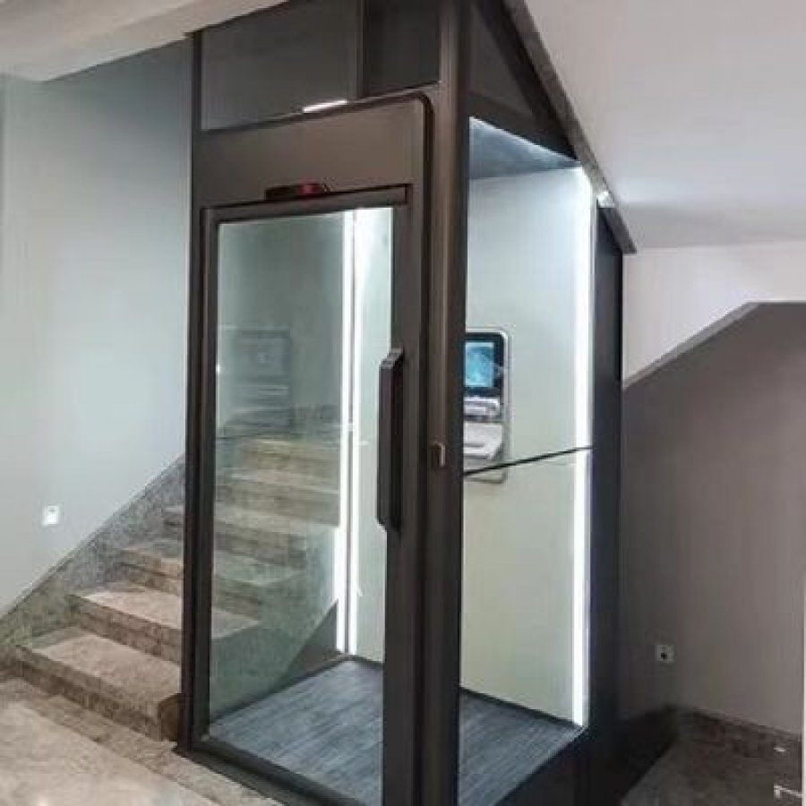
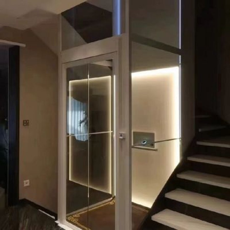
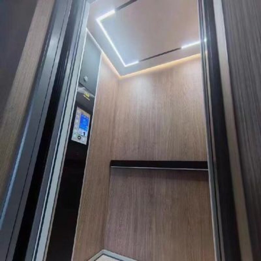
Inside a home lift there are only two things a household touches: the cabin it stands in and the door it waits behind. Everything else — pump, cylinders, controller — is judged only by how the cabin arrives. This model offers a 304 stainless steel cabin or an aluminium alloy cabin, with automatic landing doors quoted as part of the specification. On a home lift with automatic sliding door panels, that door is the part of the machine seen most often and doing the most work.
304 stainless steel cabin
Stainless steel survives a busy hallway: it takes knocks without showing every one, wipes clean and does not need repainting. It is also the heavier option, which matters if the shaft is kept as slim as the house allows.
Aluminium alloy cabin
An aluminium alloy cabin is the lighter panel, and on a residential structure that weight difference is the reason to choose it. Colour and finish are decided per project, so a cabin can be specified to sit with a hallway rather than announce itself in it.
Automatic landing doors
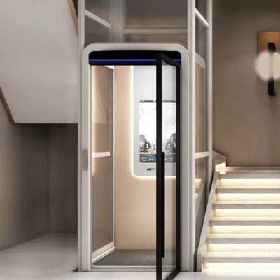
The landing door is driven open and closed as part of the run rather than worked by hand. Opening width, handing and the space reserved for the operator are project dimensions, confirmed on the drawing with the shaft and the cabin.
What the door adds to the daily routine
An automatic door changes the order in which things happen. The passenger steps into a cabin whose landing door has already opened, travels, and steps out at a floor where the door opens in front of them. Nothing has to be held, pushed or propped, and the lift is never left with a door standing open because the last user was carrying something.
The same door is also the part that will need attention first. A door operator is a driven mechanism, and driven mechanisms wear: it is the component most likely to be adjusted at a service visit. The upkeep section below sets out what that means in practice.
The ride itself
At commissioning, two things are worth standing in the cabin for. Check the arrival first: the cabin floor and the landing floor should meet without a step. Then check the start and stop at either end of the run, which should happen without a jolt. Both are functions of setup rather than of size, and both are settled before handover.
Safety devices, and how an installation is accepted
The safety device named in this model's specification block is an emergency stop button: a deliberate, physical control, where the person in or beside the cabin decides the lift should not move and presses it. On a home lift it is the control a household asks about first, and the one to demonstrate at handover so nobody has to work it out in the moment they need it.
It is not a substitute for the rest of the arrangement. A lift that is safe to live with is safe because several things agree: a landing door that is part of the run, a cabin that arrives level, a drive that is isolated for maintenance, a stop control within reach. The checklist below confirms each of those on the finished installation.
What the button does, and what it does not
Pressed, an emergency stop takes the drive out of service and the cabin stops. How the lift returns to normal afterwards is a commissioning detail and should be explained in person: which control resets it, whether the cabin has to be brought to a landing first, who to call if it repeats.
The button does not solve a lift that stops for another reason. A lift that will not start is usually reporting something: a door not closed, a supply interruption, a call that has not registered. Treating the stop control as a reset for every problem is the habit worth discouraging from day one.
The walk-through at handover
Seven checks cover the parts of a hydraulic home elevator a household will rely on. Each is a physical test rather than a document, and each belongs with the person who will use the lift, and not just the installer.
Acceptance walk-through
Ticked so far: 0 of 7
Terms worth agreeing before the lift arrives
Two questions are best answered in writing rather than at handover. The first is what happens at the threshold during a supply interruption: that behaviour belongs to the installation being delivered and should be described for your model rather than assumed from a general rule. The second is the maintenance interval, including the door operator, the component with the most to wear. Both belong in the same document as the drawing.
Warranty on this model runs 1 year on the equipment supplied. The period, its start point and what is excluded are stated on the order confirmation, which is worth reading as carefully as the specification.
From enquiry to handover: how a home lift installation runs
A residential lift project fails on information long before it fails on hardware. Each step below carries one question: what has to be true before the next step can start. Read that way, the schedule stops being a promise and becomes a list of things that are either settled or not.
-
Survey: the six figures that fix the design
Six answers shape everything after them: the number of landings, the floor-to-floor height between each pair, and the clear headroom above the top landing. Then the opening width at each floor, the position available for the power unit, and what the supply at the shaft actually is. Photographs of the space and the board shorten this step; a plan drawing shortens it more.
-
Approval drawing: the document the lift is built to
The drawing shows the shaft, the cabin, the landing door positions, the cylinder arrangement, the power unit and the finishes. It is where the 0 m pit and the 3 m clearance stop being figures on a page and become dimensions on your building. Nothing should be manufactured before it is signed.
-
Manufacture: 45 working days from the approved drawing
Delivery is quoted at 45 working days from the agreed drawing, with a supply ability of 20 sets per month. The clock starts on the approval, not the enquiry, which is why a late approval costs more time than it looks like it should.
-
Packing and shipping
The lift travels in an export non-fumigation wood box, which matters in markets where fumigated packing attracts inspection or delay. Send the destination port or city with the enquiry so shipping and any installation arrangements are quoted in the same reply as the equipment.
-
On site: structure, cylinder, power unit, cabin, doors
Installation follows the drawing: the shaft is prepared and checked for plumb and clear openings, the guide arrangement and hydraulic circuit go in, the power unit and control panel are positioned and connected, then the cabin and landing doors. The doors are the last mechanical item and take the most adjustment, because every landing is set individually.
-
Commissioning and handover: the walk-through in the section above
Levelling is set at every landing, the door cycle is adjusted at every landing, the stop control is tested in front of the household, and the installation is run through the acceptance list above. The documents that come with it — what was supplied, the warranty terms, who to contact — close the project, and are what a future buyer will ask for.
Two of those steps are worth protecting in the programme. The survey is where a project is made easy or expensive, and the approval drawing is where a change is still a drawing change rather than a manufacturing change. Everything after it is execution.
Upkeep, the door operator and what the warranty covers
A home lift is a small machine that runs a few times a day, so it needs occasional attention rather than constant care — aimed at the right parts. Three do nearly all the work: the landing door operator, the hydraulic power unit, and the levelling arrangement that decides whether the cabin meets each floor cleanly. The fourth item is not a component at all, but the paper that says what is covered.
The door operator is the part that wears
A door driven open and closed on every run accumulates more movement than any other part of a home lift. It is the component most likely to be adjusted at a service visit, and the one to test at every landing: listen for a change in the way it travels, and watch that the opening is fully presented each time.
The power unit wants to be clean and dry
The power unit on this model sits where the drawing agreed, with a 4.7 kW motor and the oil side of the drive. Keeping that position clean, ventilated and free of stored goods protects the equipment and the access a service visit needs. Weeping joints at the unit, the cylinders or along the pipe route are what to look for.
Levelling at every landing
Microprocessor control holds the cabin level with each floor, and it is worth checking after any change in the house: a new floor finish at one landing, a heavier load than usual, a cold season. A lift that has developed a small step at one landing has not become unsafe; it is telling you it wants setting again.
What the warranty covers
Warranty on this model is 1 year on the equipment supplied. The start point and exclusions are set out on the order confirmation, and the maintenance interval that keeps the cover meaningful is agreed at handover rather than left to be discovered.
Recording a service visit
A one-page record per visit is enough: the date, what was checked, what was adjusted, anything noted but left alone. Two benefits follow. A change in behaviour shows up as a trend rather than a surprise — a door needing adjustment every visit is telling you something a single visit cannot. And a written record is what turns “the lift has always been serviced” into evidence when the house is sold.
Converter for service notes and drawings
=
=
=
Reference points from this model: 14.5 m is about 47.57 ft, 3 m is about 9.84 ft, and 2.9 m is about 9.51 ft. The converter is a convenience for notes and conversations; the drawing and the nameplate are the dimensions that govern the lift.
Questions that come up before an order
The questions buyers ask about this model, answered from its own specification block and its own supply terms rather than from the category in general.
Does an automatic door hydraulic home elevator suit a five-floor house?
That is the shape this model is quoted for: 5 stops and up to 14.5 m of travel, measured floor to floor between the lowest and highest landing. Five stops in a house with ordinary storey heights uses a good part of that travel; five stops in a compact house much less. Measure the sum of the floor-to-floor heights, not the height of the building.
What does a 0 m pit mean when the floor is already finished?
It means the lowest landing needs no recess. Nothing is dug below the cabin, so a finished ground floor is not cut open and the drainage and making-good an excavation brings are not in the programme. The floor still has to carry the equipment standing at that level, confirmed as part of the drawing.
How much headroom does the lift need at the top?
3 m of clear height above the top landing. In practice this decides where the shaft can go, because the space above the top floor is often already occupied — a stair void, roof timbers, a service run, a landing window. Check that envelope before the shaft position is agreed.
Will a 4.7 kW motor really run on a domestic supply?
This model is quoted at 220 V, 50 Hz single phase with a 4.7 kW motor, so it is designed around the supply a house already has rather than a three-phase service. The circuit itself — protection and conductor size — is sized by a qualified electrician from the site and local requirements.
What happens at the door if the power fails mid-journey?
That behaviour depends on the arrangement delivered for your installation, and this page deliberately does not quote a general rule. Ask for it in writing with the order: what the cabin does, what the landing door does, how passengers are brought to a floor.
How many landings can it serve, and how far can it travel?
Five stops and a quoted maximum travel of 14.5 m. A stop is a landing the lift serves, so five can be a ground floor plus four upper floors, or a basement plus three. A sixth landing, or a travel beyond 14.5 m, sits outside this model and is answered with a different specification rather than a stretched one.
Which cabin should I choose — 304 stainless steel or aluminium alloy?
Stainless steel is the harder-wearing finish and the heavier one; an aluminium alloy cabin is lighter, which matters when the structure carrying the lift is kept slim. Both are offered on this model, and the choice comes down to the surroundings the cabin has to sit in and how much weight the shaft can carry. Either is fixed on the approval drawing.
Can this model be supplied with manual landing doors instead?
This page describes the model as quoted, with automatic landing doors and an emergency stop button. The comparison earlier on this page sets out where automatic and manual doors behave differently; if a manual arrangement is what your project needs, raise it at the enquiry stage and the answer comes against your site.
What upkeep does the automatic door need?
It is a driven mechanism, so it is the part of a home lift most likely to be adjusted at a service visit. The routine is small: listen to it at every landing, watch that the opening is fully presented each time, and have it adjusted when either changes. The interval is agreed at handover.
What are the supply terms, and what does the warranty cover?
Minimum order is 1 set, supply ability 20 sets per month, delivery 45 working days from the approved drawing, payment terms T/T and L/C, and the lift ships in an export non-fumigation wood box. Warranty is 1 year on the equipment supplied, with the start point and exclusions on the order confirmation. The commercial block at the top of this page carries the same terms.
What to send for a quotation on this lift
A quotation for a made-to-order home lift is only as firm as the information behind it. Send the ten items below and the reply can be a specification with a price band and a delivery date, rather than a range with conditions attached.
Enquiry checklist
Ready to send: 0 of 10
The count is for your own file; nothing on this page is submitted anywhere. The commercial terms — minimum order, price band, payment terms, supply ability, delivery time and packing — are maintained in the specification block at the top of the page.
What comes back
The travel is checked against the 5 stops and 14.5 m quoted for this model, the headroom against the 3 m clearance, the base against the pitless arrangement, the site supply against the 220 V, 50 Hz single phase requirement. What returns is a drawing showing the shaft, the cabin, the landing doors, the cylinder arrangement and the power unit position, with the commercial terms and a delivery date counted from the approved drawing.
Design, shipping, installation and after-sales are arranged per project rather than sold as one package, so the destination matters as much as the dimensions. Send the port or city with the measurements and those arrangements arrive in the same reply.
Send the landings, the headroom and the supply
Three lines are enough to start. We will check them against the 5 stops, the 14.5 m travel, the 0 m pit and the single phase supply, then come back with a drawing and a firm proposal.
Printable site survey sheet
The same questions from the sections above, on one sheet, for the person standing in the house with a tape measure. Print it, tick as you go, and the answers become the enquiry rather than notes to write up later.
Home lift survey — ten measurements
Measured so far: 0 of 10
The tick boxes work on the page and stay in your browser.
If a measurement is one this page cannot answer, write it down as it is. That includes a shaft formed in an unusual wall, a level open to the weather, or a supply that is neither single phase nor three-phase. A stated gap is easier to design around than a filled-in guess.
Want to Know more details about this product
Similar Products