 English
 Español
Categories
Contacts
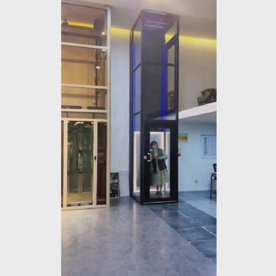
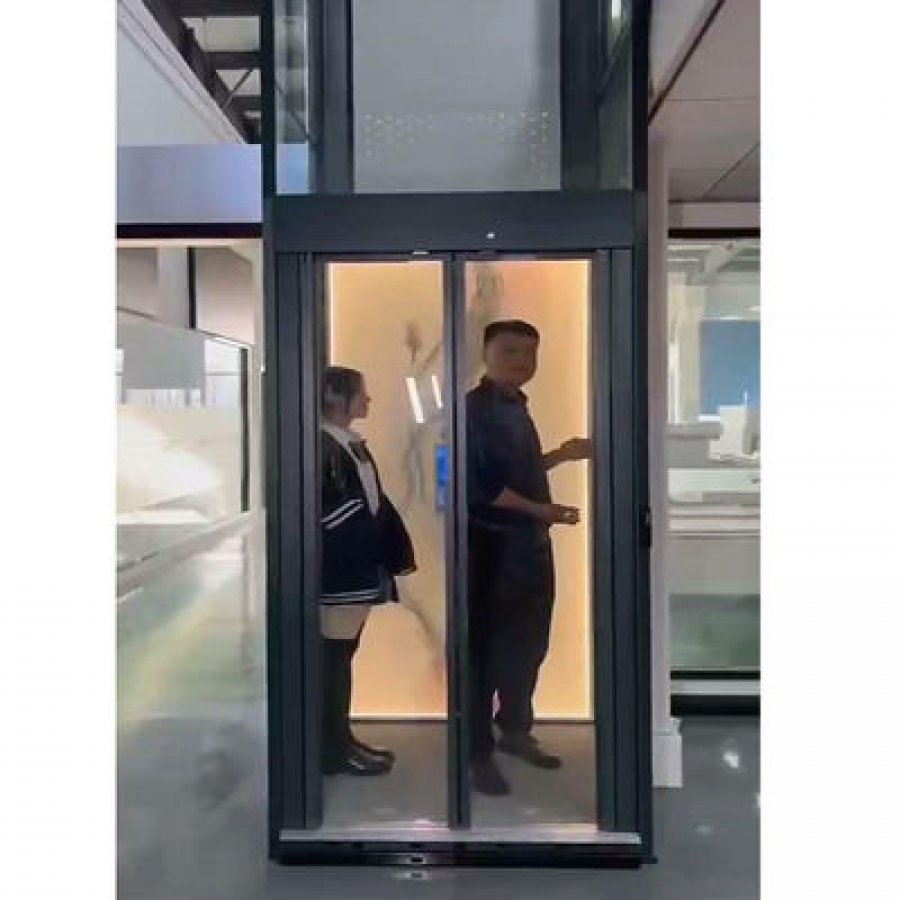
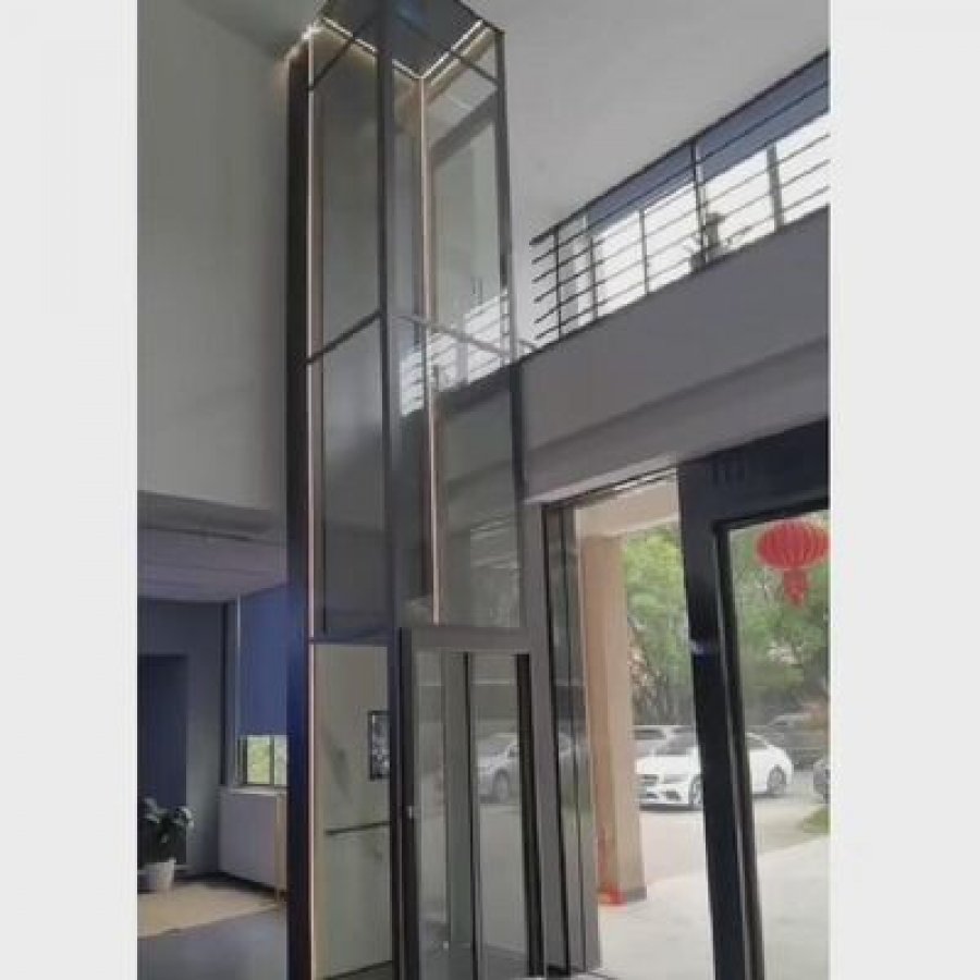
Geared Traction Elevator for Office Buildings: 500–1000 kg, 0.6–1 m/s
Product Details:
Brand Name
YIMEISITE
Place of Origin
China
Payment & Shipping Terms:
Minimum Order Quantity
1 set
Price
USD 10,000-20,000 Per Set
Payment Terms
T/T,L/C
Supply Ability
10 sets
Delivery Time
45 working days
Packaging Details
Export non-fumigation wood box.
| Certifications: | CE, ISO | Warranty: | 1 year |
| Additional Features: | Customizable design options | Drive System: | Gear and motor |
| Travel Height: | up to 50 feet | Control System: | Microprocessor-based |
| Installation: | Indoor or outdoor | Power Supply: | 220V, 50Hz, Single phase |
| Capacity: | 500-1000 kg | Safety Features: | Emergency stop button, safety sensors, door interlocks |
| Speed: | 0.6-1 m/s | Type: | Traction |
| Highlight: | platform traction type elevators,office traction elevators,office traction type elevators | ||
Product Description
Office & commercial traction elevators · YIMEISITE
A geared traction elevator for offices that is specified on travel, load and site conditions, not on adjectives
This page is for the people who have to sign off the shaft, the machine room and the power supply: general contractors, MEP coordinators and property managers. The unit described here is a geared traction elevator for office and commercial buildings with a rated load of 500–1000 kg (1100–2200 lbs), a speed of 0.6–1 m/s, shaft travel of up to 50 ft (about 15 m) and a 220 V, 50 Hz, single-phase supply, controlled by a microprocessor-based panel. Certification on the current specification sheet is CE and ISO, and the warranty is 1 year.
What follows is the decision content that the usual "geared vs gearless" explainer never gets to: whether your building can actually take this machine, what has to be true before the order is placed, what to measure on site, and what to check at handover.
The short version
- Good fit: low- and mid-rise office or commercial buildings, rated load 500–1000 kg, travel inside 50 ft, frequent stops on short runs, single-phase power already available at the shaft.
- Poor fit: travel beyond 50 ft, loads above 1000 kg, freight-style duty with goods traffic, or buildings that demand high-speed high-rise performance and a sealed, oil-free machine.
- Confirm before you order: rated load and car size, floor-to-floor heights and total travel, clear shaft and machine room dimensions, pit depth and top clearance, and the phase and voltage actually present at the site.
1. Is a geared traction elevator the right choice for your building?
A geared traction elevator uses an induction motor with a reduction gearbox to turn the sheave. That one mechanical fact decides almost everything else: where the machine is mounted, how much room it needs, how it sounds, what it costs to run, and what it costs to buy. For a building with a rated load of 500–1000 kg, a travel ceiling of 50 ft and a speed setting of 0.6–1 m/s, the geared arrangement is still an efficient answer, and in some projects it is the cheaper one. In others it is simply the wrong tool.
The three cards below sort your project into one of three states. The middle column is not a rejection: it means the project needs a different drive, a different page, or a site change before this specification can be applied.
Suitable
- Office, commercial, institutional or mixed-use building, low to mid rise
- Rated load between 500 kg and 1000 kg for staff, visitors and light trolley traffic
- Total shaft travel of 50 ft (about 15 m) or less
- Travelling speed of 0.6–1 m/s is acceptable for the number of stops involved
- A machine space above or near the shaft is available
- 220 V, 50 Hz, single-phase supply can be brought to the machine position
Not suitable
- Total travel beyond 50 ft
- Rated load above 1000 kg, or duty dominated by goods and trolley traffic
- High-rise cores that need speeds well above 1 m/s to keep waiting times down
- Buildings that cannot accept a gearbox, its oil and its periodic oil service
- Projects where the shaft or top clearance cannot be provided and no alternative layout is possible
Ask our engineers
- Rated load and car size against your actual passenger and trolley pattern
- Total travel worked out from real floor-to-floor heights, not from a floor count
- Clear shaft dimensions, pit depth and top clearance against the approved drawing
- Phase, voltage, frequency and available supply capacity measured at the intended machine position
- Door opening width for furniture, stretchers or cleaning equipment
- Whether an outdoor shaft is exposed to driven rain, and what weather protection is needed. Contact our engineers.
A word on travel: 50 ft is shaft travel, not a floor count. Divide it by your own floor-to-floor height. At 2.7 m per floor it covers about five stops, at 3.0 m about five, and at 3.5 m about four. Work this out on the drawing before the drive type is fixed, because the answer changes the specification more often than any other input.
2. How a geared traction drive moves a car
Four components carry the load, and each one has a site consequence you can see before delivery.
The geared arrangement drawn on a machine beam above the shaft. The two dimensions that decide feasibility on a real project, top clearance and pit, are site-specific and are fixed on the approved drawing.
- The traction machine turns the sheave. An induction motor runs at a speed that is far too high for a lift car, so a reduction gearbox brings it down to the rope speed that produces 0.6–1 m/s at the car. The trade is simple: the gearbox lets a smaller, cheaper motor move a 500–1000 kg load, and in exchange it adds an oil-lubricated component that needs scheduled attention.
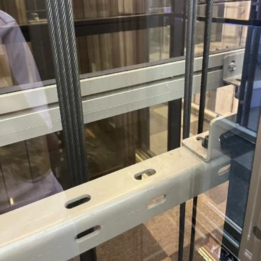
- The sheave carries the load by friction. Ropes pass over the sheave rather than winding onto a drum, so nothing runs out of rope as the car travels and the lift height is not limited by drum capacity. Traction depends on rope tension, groove condition and the load ratio between car and counterweight, which is why rope tension equalisation is part of commissioning.
- The counterweight halves the work. Because the counterweight balances the car plus roughly half the rated load, the motor only has to move the difference. That is what makes a single-phase 220 V supply practical at this load and speed.
- The safety chain stays mechanical. Governing, safety gear and buffers do not depend on the controller being healthy. Keep that separation in mind when you review the drawing: the electrical safety devices on the specification sheet sit on top of a mechanical chain, not instead of it.
Three consequences follow from this arrangement, and all three show up as site requirements rather than as marketing claims. First, the machine has mass, so it needs a structural position that can take it. Second, the gearbox needs oil and access for checking it. Third, the drive is happiest when the load is moderate and the stops are close together, which is precisely the duty an office building with a 50 ft travel ceiling creates.
3. Geared vs gearless for an office building
The geared vs gearless elevator question is usually answered as a technology lecture. On a real office project it is a procurement question with three inputs: how far the lift travels, how often it stops, and how much money is available at the start compared with the running years. The table below compares the two arrangements on those inputs, at the load and speed class this page covers.
| Decision point | Geared traction | Gearless traction |
|---|---|---|
| Drive arrangement | Induction motor with a reduction gearbox turning the sheave; a well-established arrangement at low and mid rise | Compact permanent-magnet motor driving the sheave directly, without a reduction gearbox |
| Machine position | Above the shaft on a machine beam, or in a machine room next to the shaft head | Frequently mounted in the shaft head itself, so a separate machine room is often avoided |
| Noise and vibration | Gear mesh and oil add a small amount of noise and vibration; irrelevant in a plant area, noticeable if the machine sits next to a meeting room | Lower noise and vibration, which matters when the machine is inside the shaft head of an occupied floor |
| Ride comfort | Smooth for a 0.6–1 m/s machine when the guide rails are straight, ropes tensioned equally and the gearbox is in good order | Easier to tune for the same comfort at this speed, with faster and repeatable levelling |
| Maintenance routine | Includes gearbox oil level checks and periodic oil service on top of the normal rope, brake and guide checks | Sealed bearings instead of oil; routine is dominated by brake, rope and guide inspection |
| Energy at low rise | Higher losses through the gearbox and a larger motor, offset by a lower first cost on the machine | More efficient per trip, with the price difference paid back over the life of the building |
| First cost | Usually the lower equipment cost at 500–1000 kg and travel inside 50 ft | Higher equipment cost, which some projects recover by dropping the machine room |
| Best-fit building | Low and mid-rise offices, commercial or institutional buildings with 500–1000 kg load and short, frequent runs | Taller or quieter buildings, projects where the machine room cannot be provided, higher travel and higher speed |
| Cost of choosing it wrongly | Over 50 ft travel or above 1000 kg, the machine is worked beyond the arrangement it was built for: shorter service intervals, more heat and more noise | On a short low-rise run at 500–1000 kg, the extra first cost buys performance the trip profile cannot use |
If you only keep one line from this section, keep this one: at 50 ft of travel or less with a 500–1000 kg office load, the geared machine is normally the economical specification; the gearless drive earns its higher price when travel grows, speed rises, or the machine cannot be separated from occupied space.
Three decision rules that follow from the table
- Travel decides the drive. Inside 50 ft, the geared machine is inside its comfort zone. Beyond it, look at a gearless drive and a different specification before you look at discounts.
- Duty decides the service plan. Frequent short runs at 500–1000 kg mean more starts per hour, so brake adjustment and rope inspection intervals should be set from the traffic study rather than from a generic calendar.
- The building decides the room. If a machine room can be provided above the shaft, the geared machine needs nothing else. If the room cannot be provided at all, gearless is the answer and the site constraints change with it.
What a 0.6–1 m/s office lift actually does in a working day
Traffic is where an office specification is usually decided, and it is worth doing the arithmetic before the drive type is fixed. On a short run inside 50 ft, a car travelling at 0.6 m/s takes roughly two seconds of travel per floor between adjacent landings, and at 1 m/s closer to 1.2 seconds. Door open and close times, passenger transfer and call answering add far more to a round trip than the travel itself, which is the reason that going faster on a five stop shaft buys almost nothing in waiting time, while a badly set door time costs several seconds on every single trip.
Two conclusions follow for a 500–1000 kg office lift. First, choose the speed from the number of stops and the distance between them, not from the top of the published band. Second, spend the effort on door timing, call allocation and levelling accuracy, because those are what a tenant experiences twenty times a day.
How to compare two geared offers line by line
Offers for the same rated load and travel can differ by several thousand dollars without any of them being dishonest. The differences sit in the items below, so compare them one by one rather than by the headline price.
- The travel actually quoted. One supplier quotes travel, another quotes the number of floors. Convert both to metres or feet before comparing, because a five stop building with a tall ground floor can sit outside the 50 ft ceiling.
- What is inside the car. Handrail, ceiling, lighting, flooring and the car operating panel change the price and the lead time, and they are what the tenant sees every day.
- Doors. Landing door type, finish and clear opening are quoted separately by some suppliers and included by others.
- Control panel and signals. Check which panel, which call arrangement and whether fault memory is readable by the maintenance team.
- The scope split. Confirm in writing who supplies the guide rails, the machine beam, the travel cable, the electrical feed, unloading and installation labour.
- Documents. Approval drawing, test record at handover and the maintenance schedule should be listed in the offer, not promised verbally.
4. Key specifications and unit conversion
These are the values published for the office traction elevator on the product page and its specification sheet. Use them for planning, then confirm the final figures on the approved drawing, because car size, stops and shaft dimensions are fixed per project.
| Parameter | Specification | Where it changes your project |
|---|---|---|
| Rated load | 500–1000 kg1100–2200 lb | Sets car size, door width and the structural load at the machine beam |
| Speed | 0.6–1 m/s118–197 fpm | Sets waiting time on a short run and the rope and brake duty on frequent trips |
| Travel height | up to 15.2 mup to 50 ft | Measured shaft travel, not floor count; divide by your floor-to-floor height |
| Power supply | 220 V, 50 Hz, single phase | Single-phase feed keeps the site electrical work small; confirm it is available at the machine position |
| Drive system | Geared traction (gear and motor) | Requires a machine position with access for oil checks and gearbox service |
| Control system | Microprocessor-based | Car and landing calls, door timing and fault records are set from the panel |
| Safety features | Emergency stop button, safety sensors, door interlocks | Listed on the specification sheet; the full mechanical chain is confirmed with the drawing. Contact our engineers. |
| Installation | Indoor or outdoor | An outdoor shaft changes the weather protection and the inspection schedule |
| Certifications | CE, ISO | Listed on the current sheet; project-specific local approvals stay with the buyer. Contact our engineers. |
| Warranty | 1 year | Aligns with the commissioning date, not with the shipping date |
| Brand / origin | YIMEISITE / China | Declared for customs and for the technical file |
Planning figures you can convert yourself
Two conversions catch people out when they compare offers from different suppliers. Travel is quoted in feet on one sheet and metres on another, and speed is quoted in metres per second on one and feet per minute on the other. The arithmetic is the same in both directions: multiply metres by 3.281 to get feet, and multiply metres per second by 196.85 to get feet per minute.
- 15.2 m travel = 50 ft, which is the ceiling on this specification
- 0.6 m/s = 118 fpm and 1 m/s = 197 fpm, the speed range on this specification
- 500 kg = 1100 lb and 1000 kg = 2200 lb, the rated load range
At a planning assumption of 75 kg per person, the 500 kg end of the range covers about six passengers and the 1000 kg end about thirteen. That is a planning figure only: passenger count, car size and door width are confirmed together on the approved drawing, and the certified load stays the one printed on the plate.
5. Shaft, machine room and site conditions
A geared traction machine needs three things from the building that a hydraulic lift does not ask for: a shaft that runs the full travel, clear space above the top landing for the machine and the car's over-travel, and a pit below the bottom landing. Get those three right on paper and the installation is routine. Get them wrong and the correction costs more than the lift.
The checklist below is the one our engineers use when a contractor sends a pit plan. Tick all three before production drawings are issued.
Site self-check 0 of 3
Measure the clear width and depth at every floor rather than at the bottom alone. The smallest section controls the car size. Note guide rail fixing positions and anything crossing the shaft: beams, ducts, pipes and existing services.
The headroom must take the machine beam, the car's over-travel and the counterweight path. The exact figure belongs on the approved drawing and is confirmed per project. Contact our engineers. If the building cannot give that headroom, the drive type has to be reviewed before the order, not after.
Buffers, over-travel and maintenance access sit in the pit, and the pit should drain or be sealed against groundwater. Pit depth is project-specific and is fixed on the approved drawing. Contact our engineers.
Shaft elevation with the two dimensions that cannot be improvised: top clearance above the top landing and pit depth below the bottom landing.
The other five site items that slow projects down
- Load path. The machine beam transfers the machine load plus the rope tension into the building. Structural steel frames and concrete shafts take this differently, so send the shaft construction type with the pit plan.
- Landing door openings. Confirm clear opening width at every landing, especially if the building moves furniture, medical equipment or cleaning trolleys. Door width also interacts with the car size you can use.
- Access for the machine and the car. A 500–1000 kg machine and the car panels arrive as separate items. Check the route from the delivery point to the shaft head: door widths, turning space and any lifting point above the shaft.
- Machine position environment. The machine position should be dry, ventilated and lockable, with light for maintenance and enough clearance to open the machine for service.
- Outdoor shafts. The specification allows indoor or outdoor installation. An outdoor shaft needs weather protection at the entrances and at the machine position, plus a maintenance interval agreed with the fact that the equipment sees rain and temperature swings.
On a conversion project the same three checks apply, but they are harder to satisfy. Adding a lift to an existing two or three storey office usually means finding shaft space inside the floor plate and accepting a smaller car, or building the shaft against an outside wall where weather protection becomes part of the scope. Both routes work with a geared traction elevator at 500–1000 kg and inside 50 ft of travel, provided the top clearance above the top landing and the pit can be created. Those two dimensions, not the machine itself, are what decide whether a retrofit is straightforward or expensive, so measure them before the layout is drawn.
6. 220 V single-phase power and control
The published supply for this office traction elevator is 220 V, 50 Hz, single phase. On a commercial project that is good news: the electrical contractor does not have to run a three-phase feed to the shaft head, and the supply can usually be taken from the existing distribution without a new transformer.
It also means the specification only holds if the site actually delivers that supply. The card below is the condition check we ask contractors to complete before release to production.
220 V, 50 Hz, single phase measured at the machine position
Measured, not assumed from the building's main board. Voltage, frequency and phase are recorded on the site form, with the reading taken at the position where the panel will be installed.
ConditionDedicated circuit with protective earth
The lift should not share a circuit with workshop machinery, welding equipment or large switched loads. A dedicated feed with a proper protective earth keeps the microprocessor control free of disturbances.
ConditionSupply capacity and cable size
Cable gauge, breaker rating and isolation method are calculated for your travel, load and starts per hour, and are stated on the drawing issued for your project. Contact our engineers. Send the site electrical details with the enquiry and they are fixed together with the layout.
Ask our engineersThree-phase-only sites
If the building can only provide a three-phase supply, say so at enquiry stage. The panel and drive are specified to match the supply you actually have; changing it after the panel is built costs time.
Tell us firstStandby or emergency operation
If your building code requires the lift to remain available during a power failure, that changes the electrical design rather than the lift itself. Contact our engineers. Raise it in the enquiry so the arrangement is agreed before the order, not after delivery.
Site requirementWhat the microprocessor control actually decides
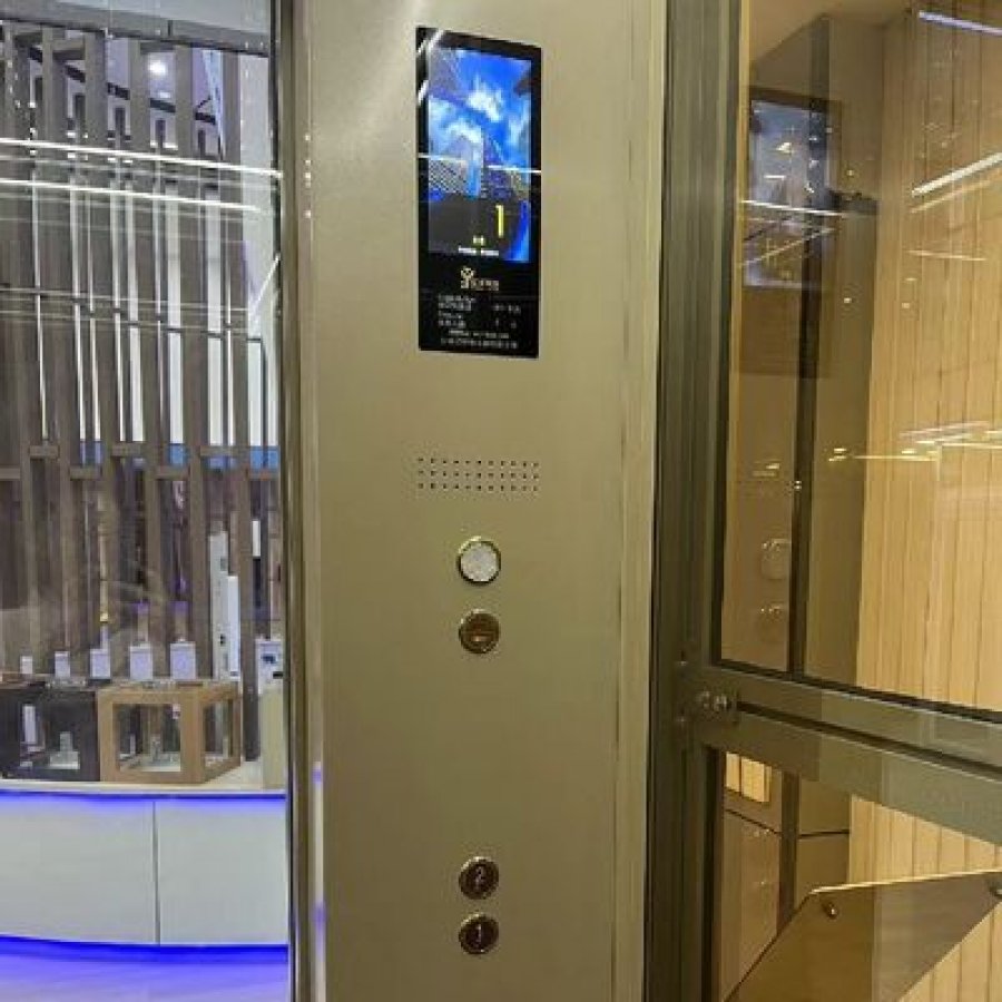
The specification sheet lists a microprocessor-based control system. Practically, that board is where the day-to-day behaviour of the lift is set: how car and landing calls are registered and answered, how long the doors stay open at each floor, how the car re-levells as passengers step in and out, and what faults are recorded for the service engineer to read.
Control panel, viewed as the service engineer sees it
- Call handling: car and landing calls registered, then served in the order set for your traffic pattern
- Door timing: open time and re-open behaviour set per landing, useful where a lobby door is used by trolleys
- Levelling: correction applied as the load changes during boarding, which matters on an office lift used in short bursts
- Fault memory: events stored for diagnosis, so a service visit starts from a record rather than from guesswork
- Parameters: stored in the panel and documented for the maintenance team at handover. Contact our engineers.
Panel layout and the parameter list are project-specific. The items above describe what the control system governs; the values are set on commissioning and recorded in the handover documents.
Three site conditions protect that panel and are worth writing into the electrical scope: keep the machine position dry and ventilated, keep it lockable, and keep the feed free of large switched loads that share the same circuit. None of the three costs much at construction stage and each of them is expensive to correct afterwards.
7. Levelling and ride quality on short runs
At 0.6–1 m/s, passengers never judge the lift by its top speed. They judge it by whether it stops level with the floor, whether it starts and stops without a jolt, and whether the doors behave. On an office lift that makes ten or twenty short trips an hour, those three things are the whole experience.
Speed setting on this specification
The working speed is selected inside this band from your travel and number of stops. Short travel with few stops does not gain anything from the top of the band, and long travel with many stops is where the upper end earns its place.
What is checked at commissioning, and what it depends on
- Levelling at every landing, loaded and empty. Stopping accuracy is checked with the car empty and with rated load, because an office lift changes load quickly during boarding. The acceptance figures come from the standard your project falls under and from the contract, and they are recorded in the commissioning report.
- Start and stop characteristics. Smooth acceleration and deceleration are set in the drive parameters, then verified over the full travel with passengers in the car.
- Door behaviour. Opening and closing time, re-open reaction and interlock function are checked at each landing, because door faults are what occupants actually report.
- Noise at the machine position. The gearbox and machine mounting are checked under running load, particularly if the machine beam shares a wall or slab with occupied space.
Comfort comes from six items, in this order of attention
The list below is the order our service engineers work through when a ride is reported as rough. It is a troubleshooting order, not a scoring system.
- Guide rail alignment and fixing. Rails that are not straight or not tightly fixed transmit every defect into the car.
- Rope tension equalisation. Unequal rope tension shows up as vibration that changes with car position.
- Machine mounting and isolation. Correct pads and a properly seated machine beam decide how much of the gearbox is heard in the building.
- Brake setting. A brake that releases late or unevenly is felt as a jolt at every stop.
- Door track and sill alignment. Cheap to correct and the most visible item to occupants.
- Landing floor finish. A sill set against an uneven floor makes a level car look out of level.
Practical point for contractors: the six items above are the reason to keep the shaft clean and the rails protected until handover. Site damage during fit-out is the most common cause of a rough ride on a machine that was correct when it left the factory.
8. Safety devices and handover checks
Three safety features are published on this specification sheet: emergency stop button, safety sensors and door interlocks. Those are the electrical devices a buyer can point to on the sheet. They sit on top of a mechanical safety chain that is confirmed on the approved drawing, and here is why that distinction matters for the person signing the handover.
Safety items to trace before handover 0 of 8
On the specification sheet. Test that the car stops and remains stopped, and that the reset procedure is documented for the building's staff.
On the specification sheet. Test each landing door: the car must not move while a landing door stands open, and the door must re-open on obstruction.
Mechanical chain item. Ask for the setting, the release test record and the make of the device. Contact our engineers.
Mechanical chain item tied to the pit dimension. Check it against the approved drawing. Contact our engineers.
Mechanical chain item. Confirm the arrangement on the drawing and test the stopping position at both ends of travel. Contact our engineers.
Confirm the pit switch, the pit ladder and the lighting arrangement at handover, together with the access procedure written into the maintenance file. Contact our engineers.
Rotating parts guarded, an isolation point for the electrical contractor, and a door that can be locked so the machine area is not a walk-through. Contact our engineers.
The plate states the certified load for your car, which is what the commissioning load test must confirm. Keep the record in the building's technical file.
Two documents should come out of this section, and both belong in the technical file: the commissioning report with the test results above, and the maintenance schedule with the intervals for brake, rope, guide and gearbox oil checks. The certificates published for this product, CE and ISO, cover manufacture; local approval for the installed lift stays with the buyer's jurisdiction. Contact our engineers.
9. Installation sequence and lead time
The published delivery time is 45 working days, and it starts from order confirmation with the drawings approved. The production clock and the site clock run in parallel, and the project is late only when the second one falls behind schedule. The timeline below shows both tracks.
Step 1 · Week 0
Enquiry reviewed and layout fixed
Rated load, travel, stops, door openings, shaft dimensions and supply details are matched to the specification. Missing dimensions are what delay an offer, so send the pit plan if you have one.
Step 2 · Order
Order confirmed and drawings approved
Minimum order quantity is 1 set, with T/T or L/C payment terms. Production dates are fixed once the approval drawing is signed, not before.
Step 3 · 45 working days
Production and inspection
Machine, car, doors and control panel are produced and assembled for inspection. Supply ability is 10 sets, so a small office order is not queued behind a large one.
Step 4 · Packing
Packing in export non-fumigation wood boxes
Machine, panels and long items are packed so they can be stored on site before the shaft is ready, which is normal on commercial projects.
Parallel site track
Shaft, machine position and power ready before delivery
The three self-check items in section 5, plus the 220 V single-phase feed, protective earth and a dry, lockable machine position. This track is on the contractor's programme, and it is the one that decides whether installation starts on the delivery date.
Step 5
Arrival, unpacking and hoisting
Check the packing list against the drawing, then move the machine and car into the shaft area. A lifting point above the shaft saves a day here.
Step 6
Shaft equipment, car, doors and wiring
Guide rails, machine and machine beam, counterweight, car, landing doors and the travel cable are installed, then wired back to the control panel.
Step 7
Commissioning, load test and handover
Levelling, door timing, brake and safety functions are set and tested, including the load test at the certified figure. Handover includes the test record and the maintenance schedule.
The single most useful date you can give a supplier is the day the shaft will be ready. On a 45 working day production cycle, a shaft that is three weeks late on a nine-week programme is not a supplier problem, and it is the delay that shows up on the project programme.
Who does what
Scope confusion is the second most common cause of a delayed installation, after a late shaft. The split below is the one we work to; it is confirmed line by line in the offer so that no item is assumed by either side.
| Item | Supplier scope | Site scope |
|---|---|---|
| Shaft and openings | Layout drawing, dimensions and fixing details | Shaft construction, landing openings, pit and top clearance as drawn |
| Machine support | Machine, beam design and fixing details | Machine beam fabricated and installed, or the room prepared to the drawing |
| Power | Control panel, travelling cable and connection schedule | 220 V single-phase dedicated feed with protective earth, measured and recorded |
| Delivery and lifting | Export packing, loading and shipping documents | Unloading at destination, storage and hoisting into the shaft area |
| Installation | Equipment, drawings and technical support. Contact our engineers. | Installation labour and site supervision, where a local team is used |
| Testing and handover | Test procedures, commissioning data and the maintenance schedule | Local inspection, approval and the building technical file |
Two items in that table decide how smoothly the job runs. The power supply has to be measured at the machine position before the panel is built, and the machine beam has to be ready before the machine arrives. Both are cheap at construction stage and both are disruptive to correct once fit-out is under way.
10. Office traction elevator FAQ
These are the questions that come back from contractors, MEP coordinators and property managers before an order is placed. Each answer states what the published specification supports and where a project figure has to be confirmed on the drawing.
The geared machine has to be mounted on a structural position with access for service, normally on a machine beam above the shaft or in a machine room next to the shaft head. Whether that position is a formal room or an open machine space depends on the building and on local requirements. Either way, plan the position, the load path and the service access at design stage, and confirm the arrangement on the approved drawing.
A geared drive uses an induction motor with a reduction gearbox, so a smaller motor moves a 500–1000 kg load at 0.6–1 m/s and the equipment cost is lower. A gearless drive uses a permanent-magnet motor without the gearbox, which is quieter, more efficient and easier to tune for a high-traffic or taller building, at a higher equipment cost. Inside 50 ft of travel with a moderate load, the geared machine is normally the economical answer.
Yes. The published supply for this specification is 220 V, 50 Hz, single phase, which is the reason the electrical scope on site stays small. Two conditions apply: the supply has to be measured at the machine position rather than assumed from the main board, and the circuit should be dedicated to the lift with a proper protective earth. If the building only provides three phase, raise it at enquiry stage so the panel matches the supply you have.
50 ft, about 15.2 m, is shaft travel measured from the bottom landing to the top landing, so the floor count depends on your floor-to-floor height. At 3.0 m per floor that is five stops; at 3.5 m it is four; at 2.7 m it is about five. Office buildings frequently have a taller ground floor, and that difference is enough to remove one stop from the count. Work it out on the section drawing before the drive type is fixed.
As a planning assumption of 75 kg per person, the 500 kg end of the range covers about six passengers and the 1000 kg end about thirteen. That assumption is for early sizing only. Car size, door opening and passenger count are fixed together on the approved drawing, and the certified load is the figure on the load plate, which the commissioning test confirms.
The specification allows indoor or outdoor installation. An outdoor shaft is a different project in three ways: the entrances and the machine position need weather protection, the equipment sees rain and temperature swings, and the inspection interval should reflect that exposure. Send the shaft construction and the exposure conditions with the enquiry so the arrangement and the maintenance plan match the site.
The published delivery time is 45 working days, starting from order confirmation with the approval drawing signed. Production and site preparation run in parallel, so the shaft, machine position and power supply can be completed while the lift is being built. On a commercial project the site track is usually the one that decides the installation date, which is why we ask for a shaft-ready date with the order.
The specification sheet lists CE and ISO, and the warranty is 1 year. Those certificates cover the product as manufactured and exported. Approval of the installed lift is granted under the rules of the country where it is installed, and that process stays with the buyer and their local inspector. Tell us at enquiry stage if a specific national standard has to be met, so it is addressed in the technical file rather than at handover.
The gearbox adds an oil check and a periodic oil service to the normal maintenance routine, which covers the brake, ropes, guide rails, doors, safety devices and the control panel. The exact intervals depend on starts per hour and on the environment, so they are set for your building at handover. What matters commercially is that the machine position must allow an engineer to check the oil level and drain the gearbox without dismantling anything.
Levelling is measured at every landing with the car empty and again with rated load, because an office lift changes load quickly while passengers board. Start and stop characteristics, door timing and interlock function are checked in the same commissioning session. The acceptance figures come from the standard your project falls under and from the contract, and the results belong in the commissioning report handed over with the maintenance schedule.
Yes, and on a commercial project it is the fastest way to close the technical questions. Send the shaft plan and section, the floor-to-floor heights, the required rated load and the supply details, and they are matched against the specification. The drawing then fixes car size, door openings, machine position, top clearance, pit depth and the electrical supply. Those are the figures the production team works to.
The published price is USD 10,000–20,000 per set, with a minimum order quantity of 1 set and payment terms of T/T or L/C. The figure covers the equipment set for one shaft; the final number moves with travel, stops, door arrangement, finishes and the destination. Civil works, the electrical feed, unloading and installation labour are normally on the buyer's side, and the split is confirmed in the offer so that nothing is assumed.
Yes, if the building can give a shaft route with the required top clearance and pit. On a conversion, the practical questions come first: where the shaft can run through the floor plate, whether a machine position fits above the top landing, and how the feed reaches that position. A smaller car inside the 500–1000 kg band is a normal compromise on conversions. Send the existing section drawings and floor plans at enquiry stage and the layout is tested against them before anything is ordered.
11. What to send for a quotation
An office traction elevator offer is only as good as the inputs behind it. The list below is the full set we need to fix a layout, a price and a delivery date. Send what you have; the items you cannot answer yet are the ones we will ask about, and answering them once is faster than answering them three times.
Send these with your enquiry 0 of 11
Office, commercial, institutional or mixed use, and how the lift will be used during the day.
The section drawing answers this in one line and settles the 50 ft question immediately.
Anywhere in the 500–1000 kg range, with the expected passenger or trolley pattern.
Including anything that must fit inside: furniture, cleaning equipment, medical trolleys.
The smallest section across all landings is the one that counts.
Both are project-specific and both are fixed on the approved drawing.
Machine beam above the shaft or a room beside it, in steel frame or concrete construction.
Phase, voltage and frequency measured at the machine position, plus the capacity available for the lift.
Required at every landing, including the upper floors and not just the entrance level.
If outdoor, describe the exposure to rain, wind and temperature range.
The site-ready date is the one that keeps installation on programme.
Commercial terms on this specification
| Term | Value |
|---|---|
| Minimum order quantity | 1 set |
| Price | USD 10,000–20,000 per set |
| Payment terms | T/T, L/C |
| Supply ability | 10 sets |
| Delivery time | 45 working days from order confirmation with the approval drawing signed |
| Packaging | Export non-fumigation wood box |
| Brand and origin | YIMEISITE, China |
| Certification and warranty | CE, ISO · 1 year |
One last point on scope. This page describes an office elevator that is ordered against a drawing: the numbers on the drawing decide the machine, the car, the doors and the electrical supply. If your project sits inside the 500–1000 kg and 50 ft envelope and the shaft head can take the machine, the geared traction arrangement is a dependable specification at this duty. If it sits outside that envelope, say so at enquiry stage and the specification changes with it, in the offer rather than in the building.
Send your pit plan, section and supply details for a layout and a price
Rated load, total travel, shaft dimensions and the power supply at the machine position are enough for us to fix a layout and answer the technical questions in one pass.
Geared traction elevator, 500–1000 kg up to 50 ft travel · 220 V single phase
Want to Know more details about this product
Similar Products