screw driven platform lift,screw‑nut drive lift,heavy‑duty platform elevator
Product Description
Screw-driven platform lift · 500–5,000 kg · up to 15 m · 2–5 stops
A heavy-load platform lift that does not need a machine room, a deep pit or a masonry shaft
A screw driven platform lift carries loads of 500 kg to 5,000 kg between two and five floors, indoors or outdoors, on a self-locking screw and nut drive. There is no counterweight, no traction sheave and no machine room, so the load path goes almost straight into the building structure instead of into a headroom box. That is what makes this machine worth considering for garages, workshops, warehouses, mezzanines and split-level houses where a passenger elevator would demand civil works nobody wants to pay for.
This page answers four questions. When is a platform-style lift the right choice, and when is it not? How do the two ends of the capacity range change the civil works? Where can the door and platform be customized? And what has to be true about the floor and the headroom before a quotation is worth signing? Every figure comes from the parameter table on this page; anything it does not state is marked as needing a drawing.
500–5,000 kg payload range
Up to 15 m travel
2–5 stops
AC or DC power supply
Indoor or outdoor installation
Self-locking screw drive
Platform Lift or Cabin Lift: Which One Fits the Job
Buyers usually arrive at this page with one of two jobs in mind. The first is moving a heavy, awkward load between levels: pallets, barrels, machine parts, feed sacks, tyres, tiles, crates, a ride-on mower, a quad bike. The second is moving a person, or a person with a trolley, between floors of a house or a small commercial building. Both jobs can be served by a screw driven platform lift, but they justify different machines, and the deciding factors are not the same.
A heavy duty platform lift of this kind is an open or partially enclosed car without a full passenger cabin. It is sized around the load and around the space the load needs to be driven in and out, not around a standing passenger holding a handrail. A cabin lift wraps the same screw drive inside a cabin with a ceiling, walls and a close-fitting door. The drive can be identical; the civil works are not, and the cost difference usually sits in the cabin, the shaft and the door rather than in the mechanism.
Three-question fit check
Answer what you already know. Anything you cannot answer today is a site question, not a machine question.
1 Is the lift being bought mainly to move goods or a trolley rather than a standing passenger?
2 Is the required travel inside the 2–5 stop range at up to 15 m of travel?
3 Can the installation point take a 500–5,000 kg load, and is a single-phase or DC feed available close enough to reach it?
Result:answer the three questions to see where this project stands.
Choose the open platform when the load matters more than the enclosure
Open platforms win on three counts: the load can overhang the platform edges during loading, the operator can load from the side as well as the front, and there is no cabin to keep clean or to size around. For a workshop moving a 1,200 kg tool post, or a warehouse lifting pallets to a mezzanine, the enclosure adds nothing the buyer wants to pay for.
The goods are loaded by pallet truck, hand truck, trolley or forklift, so the platform needs to accept wheels rather than feet.
The load is longer or wider than a person, or arrives on a pallet whose footprint is fixed.
Two or more sides need to open so that the pallet can be driven on from one side and off the other.
The site is a warehouse, garage, plant room, farm building, cellar or an outdoor yard where finish quality is not the point.
Choose a cabin lift instead when the lift is also a route for people
Once a person travels unattended, the enclosure stops being decoration. A cabin keeps clothing, hands and carried items away from the moving rail, gives the passenger something to lean on, and makes the travel feel like a ride in a building rather than a ride on a machine. If the lift is going to sit in a finished hallway inside a home, the cabin is usually what the buyer is really paying for.
The conditions that rule an open platform out
There are honest limits to this product, and it is cheaper to hear them now than after a deposit. This page publishes 2–5 stops and up to 15 m of travel, a 500–5,000 kg payload range and either an AC or a DC supply. A project that needs more than five landings is not a five-stop machine, and a project that needs uninterrupted travel past 15 m is outside the published envelope of this model.
A load per trip above 5,000 kg puts the project outside this model, and outside the range this page publishes.
Where the structure at the installation point cannot accept a load in the 500–5,000 kg class together with the platform's own weight, the fixing detail has to change before anything else.
Public, unsupervised use of the route is a different specification conversation, covering guarding, doors and controls.
When nobody can confirm the headroom and the floor build-up today, the honest answer is to survey first rather than to book a delivery date.
How the Screw Drive Moves a Load
The mechanism is old, simple and hard to argue with. A threaded steel screw stands vertically in place of a shaft. A nut, driven by the motor, rotates on that screw. Because the nut is captive on the thread, rotating it forces it to travel up or down the column, and it carries the platform with it. Nothing is hoisted by a rope, so there is no rope to stretch, no sheave to wear and no counterweight running beside the car.
That single design decision removes most of the civil works a passenger elevator would demand. There is no machine room above the travel because the drive sits at the platform, and no separate weight path on the other side of the shaft because there is no counterweight. The load reaches the building through a small number of anchor points around the screw and the guide rails rather than through a machine-room slab.
The same drive appears across the range in other configurations — see the screw driven elevator range for the versions built around a cabin rather than an open platform.
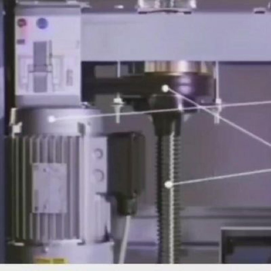
Where the parts sit: the drive travels with the platform, so the headroom only has to clear the platform and its guard, not a machine room.
The second consequence of the screw is what happens when power is lost. A screw and nut pair of this type is self-locking: the angle of the thread is shallow enough that a load resting on the nut does not spin the nut back down. The platform holds its position instead of dropping, which is why this drive is often chosen for installations where an uncontrolled descent would be expensive.
The third consequence is what you feel during travel. There is no crawling and no hydraulic pump starting under the floor, and this page states soft start and stop together with automatic lubrication. On short runs of two to five stops, the travel is direct: no counterweight means no long acceleration ramp to smooth out.
Terms used on this page
the vertical threaded column
the travelling drive element
holds position without power
keeps the platform aligned
no plant room above
floor-to-floor distance total
Why the load path stays short
In a traction machine the rope pulls the car down and the counterweight pulls it up, and both paths are gathered by the building at the top of the shaft. Here the reaction is taken by the screw along its own length, and by the guide rails as sideways restraint. That is why the anchor detail matters more than the concrete volume: a well-anchored screw and rail set tolerates a far lighter floor slab than a machine-room slab.
The trade-off is speed. The description published on this page states 0.15 m/s, so treat that figure as indicative and confirm it against the offer drawing. On a three-storey run the ride is roughly a minute, and for goods it is rarely the constraint, because loading takes longer than the trip.
If the mechanism itself is the part you need to understand before signing, the guide to screw-and-nut lifting systems goes through the thread geometry, the self-locking behaviour and where the drive is used beyond lifts.
What Changes Between 500 kg and 5,000 kg
Suppliers quote a capacity range and leave the buyer to assume that the top of the range is the bottom multiplied by ten. It is not. This page publishes 500 kg to 5,000 kg, and the two ends behave differently in the building and at the loading point. The mechanism can be the same family; the structure around it cannot be treated as the same job.
The same machine family, two different civil-works conversations
What it affects
Around 500 kg
Around 5,000 kg
Load per trip
A single sack truck, a stack of crates, one person and a trolley, a mobility scooter.
A loaded pallet, a stillage, a pallet truck with the operator's load still on the forks, machine parts on a skid.
Floor and slab
The governing question is usually point load and finish, not overall strength.
The governing question is the local load path under the screw and the rails, and whether the slab can spread it without cracking.
Anchor detail
Anchors can often be fixed into an existing slab if the survey confirms the build-up.
Anchor positions, embedment and any local thickening have to be settled before fabrication, not on site.
Loading interface
Caution and manual handling are acceptable because the load is light enough to correct by hand.
The transfer point behaves like a small goods dock: guidance, stops and a level sill matter as much as the lift.
Platform and guarding
Sized around a trolley or a single pallet; the guarding is mainly a pinching and fall-off question.
Sized around what a pallet truck has to wheel on and off, so the door and guard openings drive the layout.
Duty and cycle
Occasional use, often a few trips a day.
Repeated lifting against a production or dispatch rhythm, so the machine spends more of the day working.
What to survey first
Headroom at the top landing, floor finish, and where the power can be taken from.
Slab build-up, anchor locations, door clear opening, and the path the pallet truck takes while loaded.
Hover a row to isolate it. The table compares how the two ends of the published 500–5,000 kg range change the site conversation; it is not a substitute for the load figures in the parameter table or for a signed drawing.
Four things that scale with the load, not with the frame
Load spreading
A 5,000 kg load on a pallet truck concentrates first on the wheels, then the platform, then the screw and rails. Each step has to pass it on without denting, twisting or cracking. At 500 kg that chain is short enough that a sound existing floor is often the whole answer.
How level the sill has to be
Wheels care about level. A small step a person would not notice can stop a loaded pallet truck or tip it, so at the heavy end the landing sill is worth more engineering time than the platform surface.
How much of the day it works
A heavy lift in a live dispatch bay is a working machine. Plan the cycle so nobody waits with a load in the air, and expect the maintenance routine to be followed rather than postponed.
Where the weight is allowed to land
At the light end the load can be spread wherever the operator stands. At the heavy end its position affects the rails and anchors, so the layout should show where the pallet is expected to sit, not just how big the platform is.
Conditions that must be true at the heavy end
0 of 6 confirmed
Key Specifications, in Either Unit System
The table below collects the figures published for this machine so a buyer can check them against a site drawing without scrolling back. It carries the parameter table's values plus the speed figure stated in the description on this page. Where a figure has to be confirmed against a drawing, the table says so rather than filling the gap.
Unit system
Switching converts the published figures; it does not change them. The metric value is the source value.
Specification
Published value
What it decides on site
Capacity
500–5,000 kg1,102–11,023 lb
Whether the machine can take the pallet, trolley or load you already use, and how the rails and anchors have to be sized.
Travel height
Up to 15 mUp to 49.2 ft
The total floor-to-floor distance the machine can cover, counted from the lowest to the highest landing.
Number of stops
2–5 stops
How many landings can be served on one machine, and whether your building needs a landing the range cannot reach.
Speed
0.15 m/s29.5 ft/min
How long a trip takes. Figures are as stated in the current description; confirm the final value on the offer drawing.
Drive system
Screw drive
Self-locking travel with no counterweight and no machine room, which is what removes the headroom box.
Control system
Microprocessor-based
Landing and stop behaviour, the safety inputs, and what the maintenance routine can read back.
Power supply
AC or DC
Which feed to bring to the machine. Confirm the actual voltage and phase for your site on the drawing.
Door opening
Center or side opening
How the pallet or trolley enters and leaves, and which way the operator has to stand while loading.
Installation
Indoor or outdoor
Whether the machine needs a weather-facing finish and drainage detail, or sits in a dry internal space.
Warranty
1 year
The period covered as standard; it does not remove the need for the maintenance routine below.
Source note: capacity, travel, stops, drive, control, power supply, door opening, installation and warranty come from the parameter table and specification block on this page. The speed value comes from the description currently published here and needs drawing confirmation. Platform dimensions, pit and foundation details, headroom and door clear widths are not published and remain site-specific.
Unit converter
For checking a drawing that is drawn in a unit system you do not work in. Conversion is arithmetic only.
→lb
→kg
→ft
→ft/min
The converter does not certify a value. It only restates the number you typed in another unit, so that a drawing and a quote can be compared on the same footing.
The three specification lines buyers ask about most
AC or DC supply
Both are offered. AC is the usual choice where mains power is already on the wall beside the machine; DC suits sites that need to run from a battery or where low voltage is easier to route. Either way, the voltage, phase and protective device belong on the drawing rather than in an email.
Microprocessor control
The controller manages stop positions, call and send buttons, travel limits and safety inputs, and it is where a fault is reported. Ask for the fault indication to be explained at handover rather than discovered later.
Indoor or outdoor
Outdoor installation is published as an option, which moves attention to the finish and to drainage around the base of the screw. A sheltered yard and an exposed elevation are different environments, so say which one you have.
Doors, Platforms and Floor Customization
Two adjustments decide whether a platform lift is a good fit or a daily nuisance: which way the door opens, and what the platform is shaped like. Both are customization points here — the published door options are center or side opening, and the platform and landing arrangement are described as flexible. What follows is how to choose, not a catalogue list.
Center opening
The load travels through the middle, keeping the approach symmetrical. It suits a doorway already centred on the platform and a trolley pushed straight in, and it needs clear space on both sides for the leaves.
Side opening
The opening frees up on one side only, so the layout can hug a wall or a corner. It suits a pallet truck that arrives and leaves in the same direction, and where there is no room for a second leaf.
Neither option is better in the abstract. Settle where the operator stands while the machine moves, because that decides how much guarding and clear floor the installation needs. Draw the operator's path on the plan before choosing the door.
What "flexible floor customization" actually covers
The phrase appears on many pages in this category and means almost nothing on its own. Here is what it can usefully mean on a working installation, so that you can ask for the right parts of it.
Which landings are served
Within the published 2–5 stop range the machine is built for the landings your building has — two in a garage with a mezzanine, or a straight run of five. It cannot extend past the published stop count, so count landings before counting budget.
Platform surface and edges
A platform that only carries a trolley can be a simple deck. One that also carries a person needs a non-slip walking surface, visible edges and a guard that keeps a foot from stepping off while the machine moves.
How many sides are open
One open side suits straight-through loading; two adjacent open sides suit a corner where the pallet turns. Each extra opening adds a guard or gate that has to work with the travel, so it is a deliberate choice rather than a free extra.
Finish to match the building
Inside a finished house the visible steel, platform edge and gate finish matter as much as the capacity; in a yard or plant room they do not. Spending the finish budget only where the machine is seen keeps a project inside its allowance.
The customization boundary worth writing into the order
Stop count and travel stay inside the published 2–5 stop and up to 15 m envelope.
Capacity stays inside the published 500–5,000 kg range; if the load per trip is higher, the model is wrong, not the drawing.
Door arrangement is chosen from center or side opening; a bespoke gate geometry is a separate engineering question.
Platform size is sized from the load and the loading equipment, then confirmed against the available space — it is not a figure this page publishes.
Everything that touches the building — pit, foundation, headroom, sill level — belongs in the site drawing, because a mismatch there cannot be fixed with customization.
Foundation, Headroom and the Pitless Question
Three site conditions decide whether this machine drops into a building easily or turns into a civil-works project: what is under it, what is above the top landing, and whether a pit is acceptable. The description published on this page states a machine-room-less design with minimal pit and headroom requirements, which is a statement of intent rather than a set of dimensions. The dimensions come from your drawing.
The three decisions in one picture: how the base takes the load, how much headroom the top landing has, and whether the lowest landing is sunk or flush.
What the base has to do
The base has one job that matters: carry the screw and hold the guide rails parallel over the whole travel. Finish, kerb and drainage are secondary. With no counterweight, the load does not arrive at the top of the building the way a traction elevator's does. It does, however, arrive at the anchor points — and those are where a marginal floor shows itself first.
An outdoor base also has to shed water. A vertical screw standing on a horizontal surface is exactly the geometry that collects water at the joint, so a drained base is worth more than a beautiful one that pools.
If the machine is going outdoors, the weather-resistant arrangement is described on the indoor and outdoor screw elevator page, which sets out the same base and headroom questions with the finish and drainage detail alongside them.
What the headroom has to clear
The last metre of travel settles the headroom question. With no machine room over the travel, the only things that have to fit above the top landing are the platform, its guard and any structure travelling with it. That is why the design is described as having minimal headroom requirements — and why the figure has to be read off a drawing, because it depends on how the platform is configured at your top landing.
Three-item site self-check
0 of 3 confirmed
Tick what is already true. Anything left unticked is a survey action, not a quotation detail, and it is the part of this page most likely to change the price after the fact.
Printable site survey checklist
Ten items to walk around the installation point with. Tick them on screen, or print the list and take it with you.
0 of 10 confirmed
Safety Devices and What to Check at Handover
The safety package on this machine is described as emergency stop, overload protection, safety gear, and battery backup for emergency lowering. Those four do different jobs, and it helps to know which one you are relying on in each situation before sign-off. The final device schedule belongs on the offer drawing, so treat this list as the starting point for the handover conversation.
What each device is for
Emergency stop. Stops the machine on demand from the operator's position so that a jam, a mis-set pallet or a person in the wrong place can be dealt with at once. Its value depends on where the button is placed, so ask for the position to be marked on the drawing.
Overload protection. Prevents the machine from starting a trip with more on the platform than it is allowed to carry. It is the device that protects the drive from a load the operator did not intend to lift.
Safety gear. The mechanical device that grips the guide rail if the platform starts to move in a way it should not. It is a passive device, which is why it is checked rather than operated during a normal service visit.
Battery backup for emergency lowering. Lets the platform be brought to a landing when the normal supply is not available, so that a load is not stranded between floors. Its role is to get the platform to a landing, not to keep the machine in production service.
One property of the drive belongs in the same conversation. Because the screw and nut pair is self-locking, the platform does not run down under load when power is interrupted; emergency lowering exists so it can be brought to a landing deliberately.
Compliance and documents
The parameter table on this page lists ISO 9001. That is the certificate the page publishes, and it is a statement about the manufacturing system rather than about compliance with any national lift standard. If your project needs a conformity document for the destination market, ask for it in writing before ordering and check that it covers the product you are buying. CE and EAC documentation are not published here, so do not assume they are included.
Handover acceptance list
0 of 8 confirmed
A short warning worth repeating: none of these devices replaces keeping the load within the published 500–5,000 kg capacity or keeping people out of a moving platform's path. The machine protects against the failures it was designed for; it cannot protect against a load that was never supposed to be on it.
Installation Sequence
A screw driven platform lift is assembled on site around a few heavy parts, and most of the schedule risk sits before that, in the survey and the foundation. The sequence below keeps the surprises small: fix the geometry, prepare the base, then bring the machine to the building.
Survey and geometry
Measure the landings, the travel, the clear openings and the headroom, and agree where the screw and rails will stand on the plan. Nothing should be ordered until this step produces a drawing both sides accept, because everything after it is built from those dimensions.
Confirm the base and the anchors
Establish what the floor is made of, where the anchor points fall, and whether a sunk pit or a flush base will be used at the lowest landing. Any local strengthening, kerb or drainage detail is settled at this stage, while the concrete is still open to change.
Prepare the power route
Bring the feed to the agreed position and leave the protective device where the commissioning engineer can reach it. Whether the site is running an AC or a DC arrangement should already be fixed by now, because the two are not interchangeable at the last minute.
Set the screw and the rails
The vertical members go in first and are aligned to each other, because every later adjustment is measured from them. Plumb and parallel here is what makes the platform run quietly and stop level at every landing.
Fit the drive, platform and guards
The nut and drive unit are mounted, the platform is attached, and the guarding, gates and landing sills are fitted around the openings the load has to pass through. The platform edge and sill relationship is set at this point rather than adjusted by users later.
Wire, commission and test the stops
Landing positions, travel limits and the safety inputs are set and tested empty, then again with the working load. Overload protection and emergency lowering are operated here, so that commissioning is a real test rather than a visual check.
Train the users and hand over
The people who will actually use the machine are shown how a trip is made, what the load limit means in practice, where the emergency stop is, and what they are expected to check. Handover is where a machine stops being a delivery and starts being equipment.
Start the maintenance routine
The first routine check is scheduled at handover, with the warranty start date recorded on the same sheet. Leaving it to be arranged later is how a machine that was installed correctly ends up being maintained by memory.
What usually delays the date
The parts that slip are rarely the lift. The date is usually set by whoever has to open the floor, run the cable or agree the headroom. Two habits keep a project on schedule: get the survey drawing signed before the machine is fabricated, and do the base and power route while the site is already open for other work.
The delivery term is a commercial matter and is stated in the parameter table alongside this body. What is worth planning around is the point at which the drawing is frozen, because that is the last moment a change is cheap.
Maintenance and the 1-Year Warranty
This page describes the machine as low maintenance, with automatic lubrication, and states a one-year warranty. Low maintenance is not the same as no maintenance, and the difference matters most at the top of the capacity range, where the machine works every day. What follows is what the routine has to cover, so that the warranty period is used properly.
Keep the screw and nut clean
The nut travels the length of the screw on every trip, so anything reaching the thread — grit, metal dust, dried lubricant — is carried into the drive repeatedly. Automatic lubrication handles the lubrication side; keeping the column clear of abrasive material is a housekeeping habit that pays for itself, especially outdoors.
Check the anchors and the rails
Every load is finally passed into the building through the anchors, so their condition is the check that should never be skipped. Look for movement at the base, loosening at the fixings, and any change in how the platform sits on the rails. A shifted rail shows up first as a rougher ride or a landing that no longer stops level.
Exercise the safety functions
Emergency stop, overload protection and emergency lowering are checked by operating them, not by looking at them. Doing so turns up a lazy contact or a flat battery before it matters. Safety gear is the exception: it is passive and is checked rather than triggered.
What a routine visit should cover
Thread and nut condition, lubrication state, and the general cleanliness of the column.
Anchor tightness and the condition of the base, including drainage if the machine is outdoors.
Rail alignment and platform fit, judged by how the platform runs and whether it stops level at each landing.
Landing stop positions, travel limits and stop accuracy with a representative load on the platform.
Operation of the emergency stop and the emergency lowering function.
Condition of the platform surface, edges, guarding and gates, including the opening mechanism at each landing.
Control faults or logged indications, read at the controller rather than inferred from behaviour.
The interval for these checks should be the one in the documentation supplied with the machine and confirmed at handover, because it depends on how often the lift runs and in what conditions. A machine used a few times a day in a dry garage and one working a dispatch bay through a shift are not on the same schedule.
What the one-year warranty covers, and what it does not
The warranty period published on this page is one year. Read it with the maintenance requirement rather than separately, because a warranty that depends on a routine is only as good as the record showing it was done. Ask for the start date, the inclusions, the exclusions and the evidence expected on a claim, all before the machine is switched on.
Spare parts, response arrangements and any extended cover are commercial matters. They are not published on this page, so they should be requested in writing with the quotation rather than assumed to be included in the standard offer.
These are the questions that come up before a quotation is issued, answered from what this page publishes. Where the answer depends on your building, it says so rather than guessing a number.
What is a screw driven platform lift?
A lift whose platform is carried up and down a vertical threaded screw by a rotating nut. There is no counterweight and no traction rope, and the drive travels with the platform, so no machine room is needed above the travel. This page publishes the machine for 500 kg to 5,000 kg over up to 15 m, in two to five stops.
How much weight can it carry?
The published range is 500 kg to 5,000 kg per trip, about 1,102 lb to 11,023 lb. Choose from the heaviest load you expect plus a margin, not from a typical load, because the machine has to be right on its worst day.
How many floors can it serve?
Two to five stops, with up to 15 m of total travel. A sixth landing is a different specification rather than an option on this one, so count the landings you need before going further.
Does it need a machine room?
No. The drive is mounted at the platform, so there is no plant room above the travel and no counterweight beside it. The published description calls this a machine-room-less design, which is one reason it suits existing buildings.
Does it need a pit?
The published description states a design with minimal pit and headroom requirements rather than naming a depth. Whether you end up with a shallow pit or a flush base at the lowest landing depends on the platform arrangement and the floor, so treat it as a survey item.
Can it be installed outdoors?
Yes. Indoor or outdoor installation is published as an option. An outdoor machine needs attention to the finish and to drainage around the base of the screw, so describe the position honestly.
What power supply does it need?
The published power supply is AC or DC, so both are offered. The voltage, phase and protective device for your site are drawing items rather than values published here.
How fast does it travel?
The description published on this page states 0.15 m/s, about 29.5 ft/min. That is a working speed rather than a passenger-elevator speed. Confirm the final figure against the offer drawing, because the parameter table does not list a speed.
Is it safe to travel on as a person?
The published safety package includes emergency stop, overload protection, safety gear and battery backup for emergency lowering. Whether a person may ride on the platform, and under what conditions, depends on the guarding, the door arrangement and the local rules, so settle it with the supplier against your site.
What happens if the power fails while a load is on the platform?
The screw and nut pair is self-locking, so the platform does not run down under load when the supply is interrupted. The battery backup exists so the platform can then be brought to a landing deliberately.
How do I choose between the light and heavy ends of the range?
Choose from the load, not the price band. A 500 kg machine is normally loaded by hand or trolley, and a sound existing floor is often the whole answer. A 5,000 kg machine is loaded by pallet truck or forklift and behaves like a small goods dock, so the slab, the anchors and the door opening have to be settled before fabrication.
What is covered by the warranty?
The published warranty period is one year. Ask for the start date, the inclusions, the exclusions and the evidence expected on a claim, and keep the routine maintenance documented.
How much does it cost, and how long is delivery?
Both are commercial terms, published in the parameter table alongside this body with the minimum order quantity, packaging and payment terms. A price band is only meaningful once the travel, stop count and platform arrangement for your building are fixed.
Quotation and Delivery: What to Send
A screw driven platform lift is configured rather than picked off a shelf, so the quality of the first enquiry decides how close the first quotation lands. Suppliers who receive a list of ten facts will usually quote in one pass; suppliers who receive the words "need a lift for a warehouse" will quote a range and revise it three times. This page publishes a price band, a minimum order quantity, a delivery time, packaging and payment terms in the parameter table beside this body. What the parameter table cannot carry is your site, and that is what the following list is for.
Send these ten items for a first-pass quotation
0 of 10 ready to send
How to read the quotation when it arrives
Check three things before comparing two quotations on price. First, whether the same travel and stop count are being quoted — a lower figure for four stops is not cheaper than five, it is a different machine. Second, whether the platform size and door arrangement match the plan you sent, because those drive both the steel and the civil works. Third, whether anything you asked for has quietly become an exclusion; a quotation that excludes the base, the power route or the guarding is not comparable with one that includes them.
The most useful question to ask of any quotation is what still has to be confirmed before it becomes an order. A supplier who answers that precisely is telling you where the risk sits. A supplier who says nothing is left to confirm is either very familiar with your building or has not read the survey.
Everything published about this machine — capacity, travel, stops, power supply, door opening, installation environment, warranty and the commercial terms — sits in the parameter table beside this body. If a figure matters to your project and it is not in that table, ask for it in writing before you order rather than taking it from a brochure.
Sending a quotation request?
Include the load per trip, the landings and the floor-to-floor heights and the first reply can carry a real configuration.

 English
 Español